
High-efficiency feed permanent magnet cylinder

A technology of permanent magnet cylinder and permanent magnet drum, which is applied in the fields of magnetic separation, solid separation, chemical instruments and methods, etc., can solve the problems of being too late to deal with, destroying mechanical equipment, and that the permanent magnet cylinder cannot meet the removal of iron-containing impurities in materials, etc. Achieving the effect of high work efficiency, good reliability and good safety

Pending Publication Date: 2021-02-26
顾艳
View PDF0 Cites 0 Cited by
  • Summary
  • Abstract
  • Description
  • Claims
  • Application Information

AI Technical Summary

Problems solved by technology

[0003] Due to the scientific design of the permanent magnet cylinder, the iron removal effect is obvious. It is an earlier application of the permanent magnet iron remover. The permanent magnet cylinder shell is made of stainless steel or carbon steel. The surface of the magnetic core is stainless steel, and the interior is a permanent magnet. The permanent magnets of the core are usually ferrite permanent magnets and NdFeB permanent magnets. According to the use requirements, the corresponding types and grades of permanent magnet materials are selected; For the removal of impurities, once the flow rate is too large, or when agglomerated materials enter the permanent magnet cylinder, ordinary devices will not be able to deal with it in time, which will cause the materials with iron-containing impurities to enter the next process and damage the mechanical equipment.

Method used


Image

  • High-efficiency feed permanent magnet cylinder

Examples


Embodiment Construction

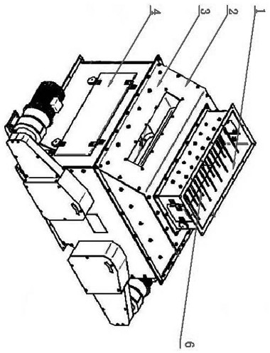
[0014] Such as figure 1 As shown, the purpose of the present invention is achieved in this way: a permanent magnet cylinder for high-efficiency feed, comprising a permanent magnet cylinder 3, is characterized in that, the permanent magnet cylinder 3 is arranged in a rectangular shape, and the permanent magnet cylinder 3 above A cover 2 is provided, and a feed inlet 1 is arranged on the top of the cover 2. The feed inlet 1 is arranged in a long strip shape, and a buffer mechanism 5 is arranged in the feed inlet 1. The permanent magnet cylinder 3 A left permanent magnet cylinder and a right permanent magnet cylinder are respectively arranged on both sides, there is a gap between the left permanent magnet cylinder and the right permanent magnet cylinder, and the left permanent magnet cylinder and the right permanent magnet cylinder are respectively provided with driving devices, The driving device is arranged on both sides of the permanent magnet cylinder 3; the left and right si...


PUM


Abstract

The invention relates to an efficient feed permanent magnet cylinder in the field of iron removal. The efficient feed permanent magnet cylinder comprises a permanent magnet cylinder body, which is arranged in a rectangular shape, wherein a cover is arranged above the permanent magnet cylinder body, a feed port is arranged above the cover in a matched mode, and is arranged in a long strip shape, abuffer mechanism is arranged in the feed port, a left permanent magnet roller and a right permanent magnet roller are arranged on the two sides in the permanent magnet cylinder body respectively, a gap is reserved between the left permanent magnet roller and the right permanent magnet roller, the left permanent magnet roller and the right permanent magnet roller are correspondingly provided with driving devices respectively, the driving devices are arranged on the two sides of the permanent magnet cylinder body, and access door bodies are further arranged on the left side and the right side ofthe permanent magnet cylinder body. The efficient feed permanent magnet cylinder is high in working efficiency, not prone to damage, good in reliability, capable of effectively removing residual iron-containing impurities in materials and good in safety.

Description

technical field [0001] The invention relates to a permanent magnet cylinder in the field of iron removal. Background technique [0002] Permanent magnetic cylinder is a kind of permanent magnetic iron remover, mainly used to remove iron impurities in dry powder materials and granular materials, and is widely used in food processing, grain processing, feed processing and fine chemical industries. [0003] Due to the scientific design of the permanent magnet cylinder, the iron removal effect is obvious. It is an earlier application of the permanent magnet iron remover. The permanent magnet cylinder shell is made of stainless steel or carbon steel. The surface of the magnetic core is stainless steel, and the interior is a permanent magnet. The permanent magnets of the core are usually ferrite permanent magnets and NdFeB permanent magnets. According to the use requirements, the corresponding types and grades of permanent magnet materials are selected; For the removal of impurit...

Claims


Application Information

Patent Timeline
IPC IPC(8): B03C1/26
CPCB03C1/26
Inventor 顾艳
Owner 顾艳
Learn More