
Bidirectional shaped charge blasting charging structure with slotted sleeve

A cutting and energy-gathering technology, applied in blasting and other directions, can solve the problems of difficulty in forming smooth wall surface, reducing the damage effect of hole wall, and the effect is not obvious, so as to achieve good explosion damage effect, reduce the degree of damage, and reduce the generation of random cracks the effect of chance

Active Publication Date: 2021-02-23
ARMY ENG UNIV OF PLA
View PDF10 Cites 6 Cited by
  • Summary
  • Abstract
  • Description
  • Claims
  • Application Information

AI Technical Summary

Problems solved by technology

[0003] The research of many experts and scholars has found that there are many defects in the principle of smooth blasting, which determine its shortcomings: the surrounding holes of smooth blasting use uncoupled charges to reduce the damage to the hole wall, thereby forming a relatively neat wall surface, However, this effect is not very obvious in soft rock formations with well-developed cracks; after blasting with uncoupled charges, the force around the hole wall is the same. In addition to forming ideal cracks, cracks will also be formed in other directions of the blast hole, making it difficult to form smooth the wall

Method used


Image

  • Bidirectional shaped charge blasting charging structure with slotted sleeve
  • Bidirectional shaped charge blasting charging structure with slotted sleeve
  • Bidirectional shaped charge blasting charging structure with slotted sleeve

Examples


Embodiment Construction

[0024] The present invention will be further described below in conjunction with the accompanying drawings. The following examples are only used to illustrate the technical solution of the present invention more clearly, but not to limit the protection scope of the present invention.

[0025] In describing the present invention, it should be understood that the terms "center", "longitudinal", "transverse", "upper", "lower", "front", "rear", "left", "right", " The orientations or positional relationships indicated by "vertical", "horizontal", "top", "bottom", "inner" and "outer" are based on the orientations or positional relationships shown in the drawings, and are only for the convenience of describing the present invention and Simplified descriptions, rather than indicating or implying that the device or element referred to must have a particular orientation, be constructed and operate in a particular orientation, and thus should not be construed as limiting the invention. ...


PUM


Abstract

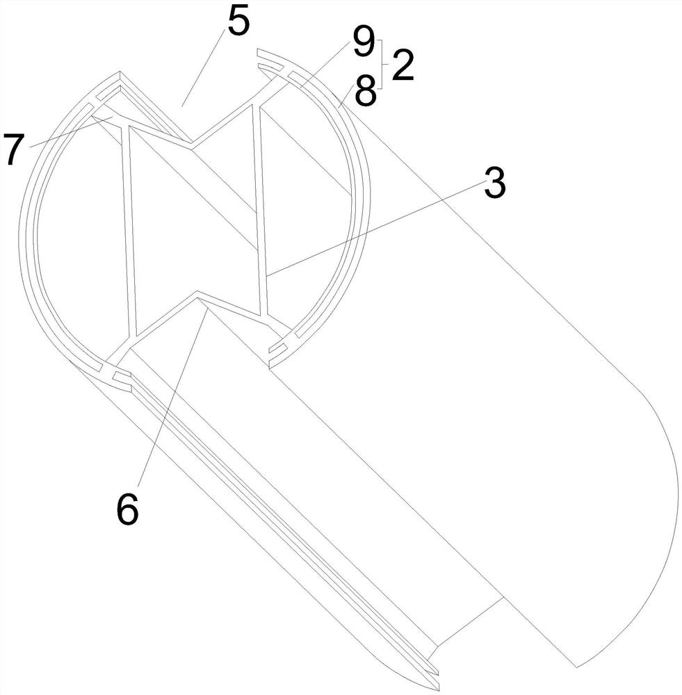
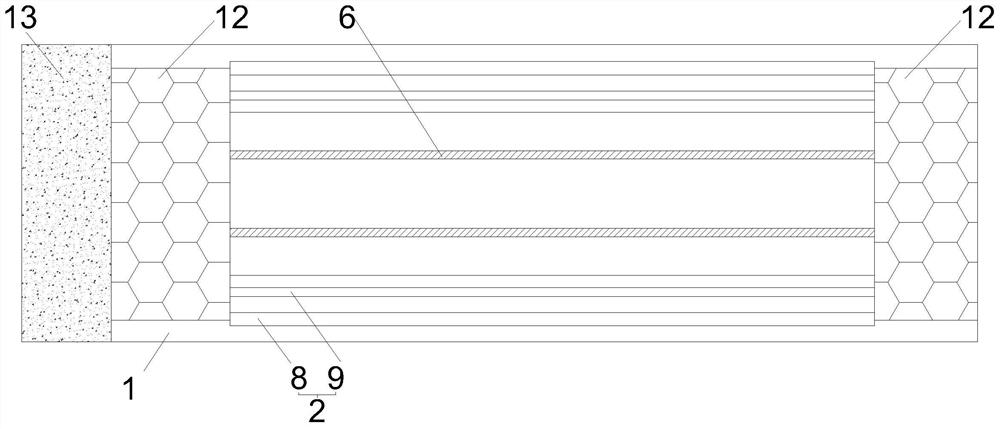
The invention relates to a bidirectional shaped charge blasting charging structure with a slotted sleeve, and belongs to the technical field of explosive blasting. The bidirectional shaped charge blasting charging structure comprises a sleeve, a shaped charge liner and explosive, wherein the sleeve is arranged in a blast hole in an inserted mode, the shaped charge liner is coaxially arranged in the sleeve and is filled with the explosive; through kerfs are formed in the two sides of the sleeve in the axial direction; the center lines of the two kerfs are coplanar with the axis of the sleeve; the two sides, close to the kerfs, of the shaped charge liner are sunken inwards in a V shape to form a wedge-shaped shaped charge groove; and the outer side edge of the shaped charge liner is fixedlyconnected to the inner wall of the sleeve through an axial supporting partition plate. According to the bidirectional shaped charge blasting charging structure, detonation energy can be concentrated in the specific direction, the utilization rate of the explosion energy is increased, damage to rock mass in other directions is reduced, and a smooth wall surface is conveniently formed.

Description

technical field [0001] The invention relates to a slit tube bidirectional energy-gathering blasting charge structure, which belongs to the technical field of explosive blasting. Background technique [0002] In recent decades, with the rapid development of the country's economic construction, various large-scale underground rock mass projects are increasing; in the excavation and blasting of large-section tunnels, the quality of the wall directly affects the quality, progress and benefits of the project; When the internal explosion blasts the rock mass within the excavation range, it will inevitably cause damage and destruction to the retained rock mass, thereby deteriorating the mechanical properties of the retained rock mass, and the most direct manifestation of the damage to the retained rock mass is to cause over-excavation; [0003] The research of many experts and scholars has found that there are many defects in the principle of smooth blasting, which determine its sh...

Claims


Application Information

Patent Timeline
Patent Type & Authority Applications(China)
IPC IPC(8): F42D1/08
CPCF42D1/08
Inventor 钟明寿周健南孔新立谢兴博刘影刘强纪冲耿汉生陈一曦王鹏
Owner ARMY ENG UNIV OF PLA
Learn More