
A mechanical lifting device

A lifting device and mechanical technology, applied in the field of machinery, can solve the problems such as the inability to meet the requirements of adjusting the height of the pedals, the high environmental temperature requirements, the low fatigue life of the gas spring, etc., and achieve convenient and comfortable operability and good maintenance. , good self-locking effect

Active Publication Date: 2021-11-02
CRRC QINGDAO SIFANG ROLLING STOCK RES INST +1
View PDF13 Cites 0 Cited by
  • Summary
  • Abstract
  • Description
  • Claims
  • Application Information

AI Technical Summary

Problems solved by technology

It has the following disadvantages: the fatigue life of the gas spring is low, which cannot meet the requirements of the driver to adjust the number of times the pedal height is adjusted; the requirement for the ambient temperature is high, and it is easy to be damaged; the maintainability is poor

Method used


Image

  • A mechanical lifting device
  • A mechanical lifting device
  • A mechanical lifting device

Examples


Embodiment Construction

[0057] The technical solutions of the present application will be described in detail below in conjunction with specific embodiments. However, it should be understood that without further description, elements, structures and features in one embodiment can also be beneficially combined in other embodiments.

[0058] In the description of the present application, it should be understood that the terms "first", "second", etc. are used for descriptive purposes only, and cannot be interpreted as indicating or implying relative importance or implicitly indicating the number of indicated technical features ; Thus, the features defined as "first" and "second" may explicitly or implicitly include one or more of these features. The orientation or positional relationship indicated by the terms "upper", "lower", "front", "rear", "bottom", "inner" etc. is based on the attached Figure 1-Figure 6 The orientations or positional relationships shown are only for the convenience of describing ...


PUM


Abstract

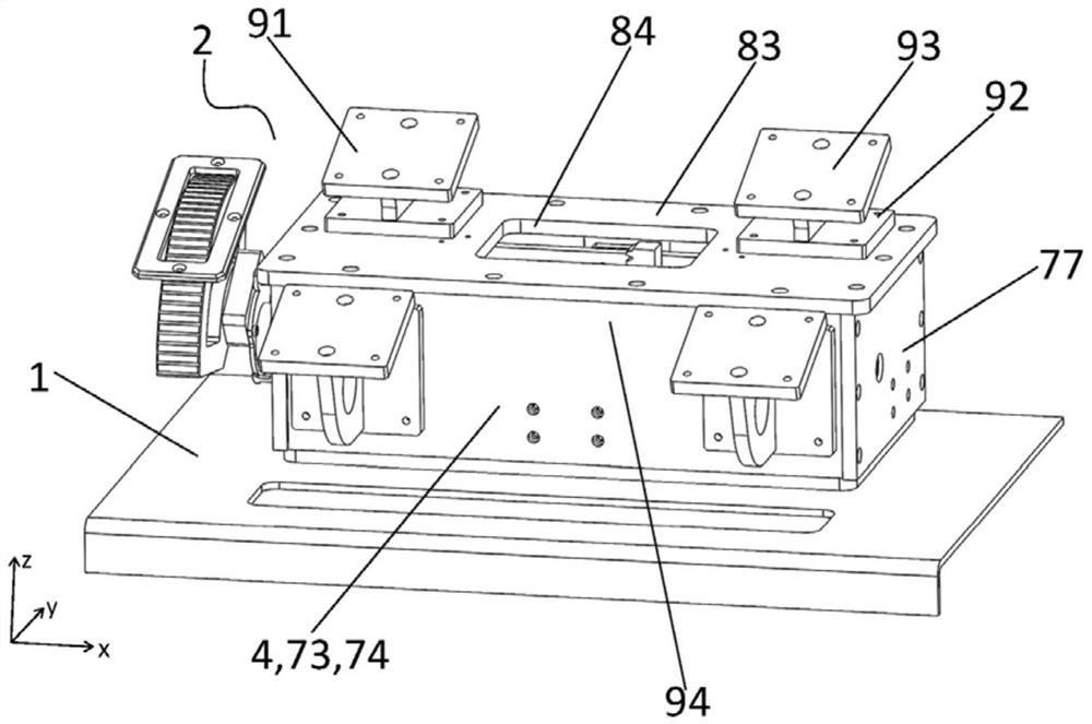
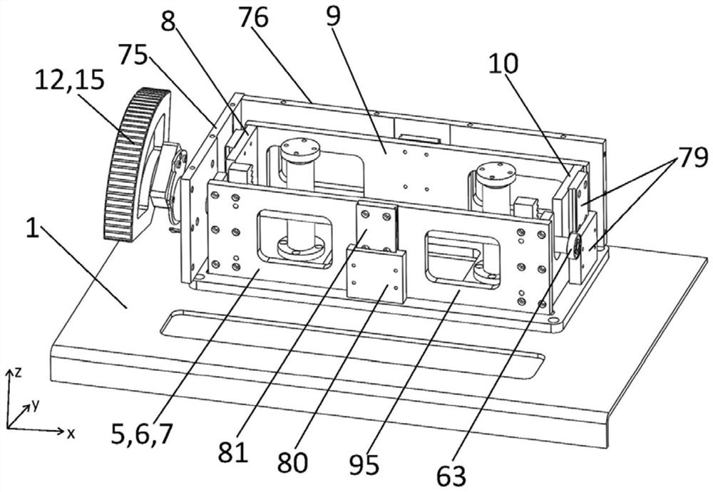
The application relates to a mechanical lifting device, comprising: a base, a driving assembly, a rotating shaft and a moving part; a rack is provided on the base; the driving assembly is connected with the rotating shaft, and is used to drive the rotating shaft to rotate bidirectionally; The rotating shaft is provided with a gear that can rotate with the rotating shaft, and the gear is engaged with the rack; the rotating shaft is rotatably installed on the moving part. The device can drive the driving assembly to rise while the moving part rises, for height adjustment.

Description

technical field [0001] The application belongs to the mechanical field and relates to a mechanical lifting device. Background technique [0002] Mechanical lifting devices, especially mechanical lifting devices in the form of pedals, are often used on locomotives. The height of the foot switch can be adjusted according to the height and body shape of the drivers and passengers to increase the comfort of the drivers and passengers and the operability of the locomotive. . [0003] CN106864471A discloses a lifting drive device for a foot switch, including a trigger mechanism and a lifting mechanism. The trigger mechanism includes a height adjustment button, a cable fixing plate assembly, a cable and a cable block, and the lifting mechanism includes an air spring, a linkage mechanism and a guide block. The guide block is connected with the pedal, and the height adjustment button moves downward under pressure, which will cause the displacement of the cable through the rotation o...

Claims


Application Information

Patent Timeline
Patent Type & Authority Patents(China)
IPC IPC(8): B61C17/04
CPCB61C17/04
Inventor 杨东军张莉林祥礼陈乐恒于津健安超张英勇夏常凯吉鹏
Owner CRRC QINGDAO SIFANG ROLLING STOCK RES INST
Learn More