A plug-resistant electrical connector

A plug-resistant technology for electrical connectors, applied in the field of plug-resistant electrical connectors, can solve problems affecting mechanical life, cracking, etc., and achieve the effects of improving mechanical life, improving wear resistance, and reducing coating wear

Active Publication Date: 2022-06-28
GUIZHOU SPACE APPLIANCE CO LTD
View PDF13 Cites 0 Cited by
  • Summary
  • Abstract
  • Description
  • Claims
  • Application Information

AI Technical Summary

Problems solved by technology

[0002] In order to ensure good electrical contact performance of the electrical connector, the contact position between the socket and the pin needs to meet a certain positive pressure, so wear is inevitable when plugging and unplugging, and in order to ensure good electrical conductivity, usually in the contact The surface of the workpiece is gold-plated, but because the hardness of gold itself is relatively soft, elements such as nickel and cobalt are usually added to the plating solution to enhance the hardness of the gold coating to improve the hardness and wear resistance of the gold coating, but factors such as corrosion resistance need to control the pores of the coating rate, the proportion of dopant elements added is limited, and the contact piece, as the core part of the electrical connector, has a direct impact on the mechanical life and reliability of the electrical connector, so that the mechanical life index of the electrical connector in the prior art is limited to 500 At the second level, with the development of military weapons and equipment, higher requirements are placed on the mechanical life of components. The conventional 500-time mechanical life of electrical connectors can no longer meet the long-life requirements proposed in more and more occasions. In addition, the elastic structure of the socket also affects the mechanical life. For example, the Chinese patent with the publication number CN104319495A provides a kind of spring claw. During the process, the claws are repeatedly expanded and retracted, and the root of the cantilever end of the claws is susceptible to concentrated stress, resulting in cracking and affecting the mechanical life

Method used


Image

  • A plug-resistant electrical connector
  • A plug-resistant electrical connector
  • A plug-resistant electrical connector

Examples


Embodiment Construction

[0022] The technical solution of the present invention is further described below, but the scope of protection is not limited to the description.

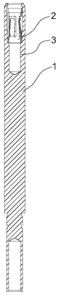
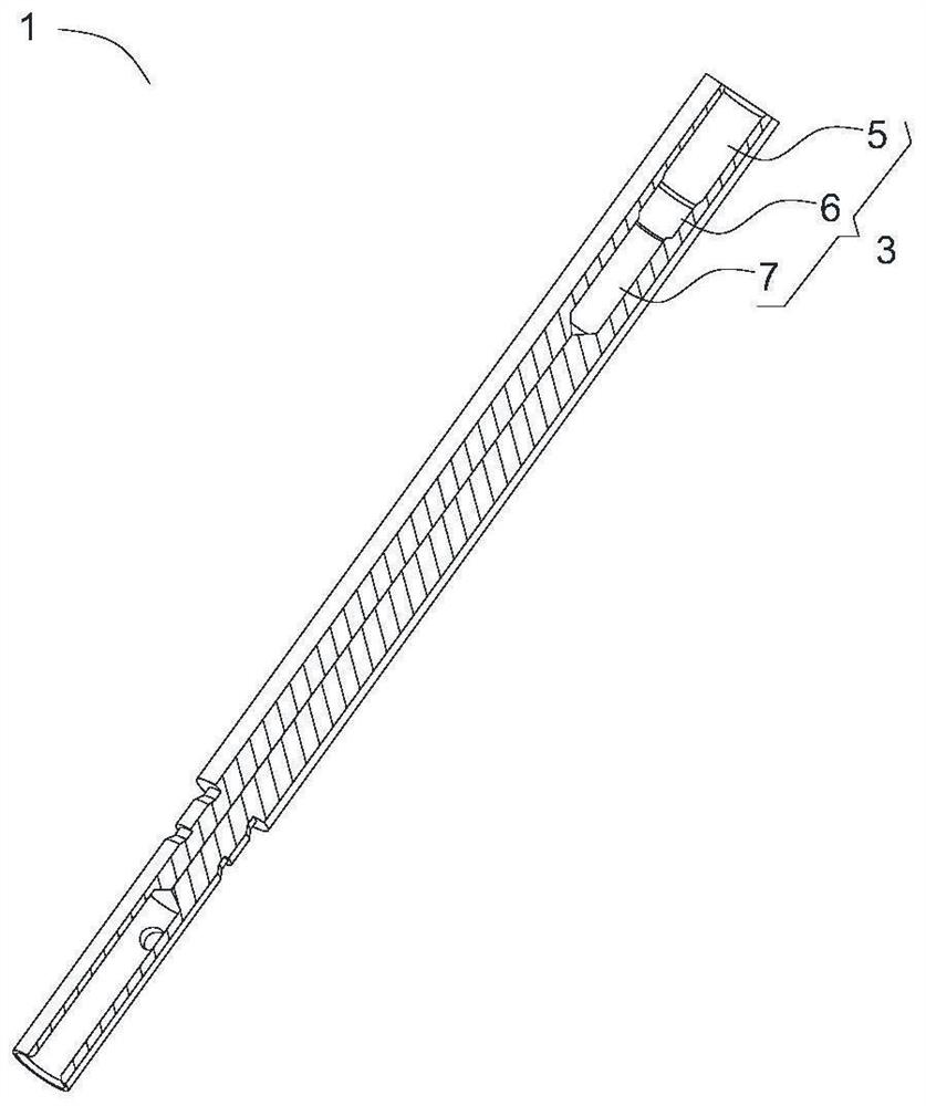
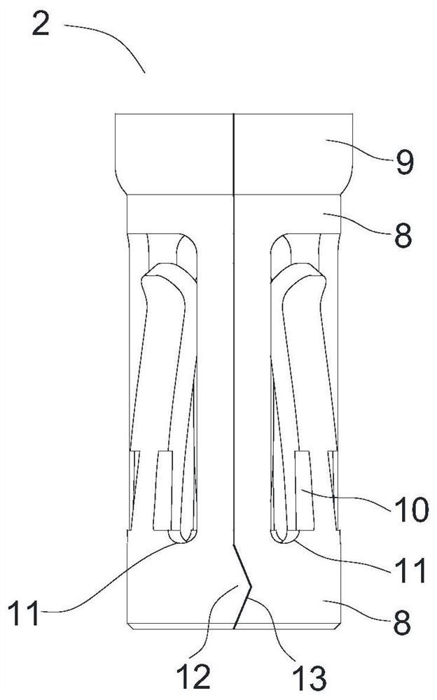
[0023] like Figure 1 to Figure 6 As shown, a plug-resistant electrical connector includes a jack fitting and a base, the jack fitting is installed in the base, the jack fitting includes a jack 1, a contact coil 2, and the jack 1 is butted One end is provided with a blind hole 3, and the contact coil 2 is installed in the blind hole 3, and the opening of the blind hole 3 is closed to fix the contact coil 2 in the blind hole 3, and the contact coil 2 is provided with several elastic claws 4, and the contact spring The coating of ring 2 is gold-graphene composite coating, and the coating of socket 1 is gold coating or gold-graphene composite coating. Using the excellent electrical conductivity and self-lubricating properties of graphene, under the condition of ensuring contact pressure, Reduce the friction coefficient to reduce the ...


PUM


Abstract

The invention provides a plug-resistant electrical connector, which includes a jack fitting and a base, the jack fitting is installed in the base, the jack fitting includes a jack, a contact coil, and the butt end of the jack is arranged There is a blind hole, the contact coil is installed in the blind hole, the blind hole is closed to fix the contact coil in the blind hole, the contact coil is provided with a number of elastic claws, and the coating of the contact coil is gold-graphene composite coating , the plating of the socket is gold plating or gold-graphene composite plating. The invention provides a plug-resistant electrical connector. By electroplating a gold-graphene composite coating on the contact coil and optimizing the spring claw structure, the mechanical life of the socket assembly is improved, and the electrical connector is further improved. mechanical life.

Description

technical field [0001] The invention belongs to the technical field of electrical connectors, in particular to a plug-resistant electrical connector. Background technique [0002] In order to ensure good electrical contact performance of the electrical connector, the contact position between the socket and the pin needs to meet a certain positive pressure, so wear is inevitable when plugging and unplugging, and in order to ensure good electrical conductivity, usually in the contact The surface of the workpiece is gold-plated, but because the hardness of gold itself is relatively soft, elements such as nickel and cobalt are usually added to the plating solution to enhance the hardness of the gold coating to improve the hardness and wear resistance of the gold coating, but factors such as corrosion resistance need to control the pores of the coating rate, the proportion of dopant elements added is limited, and the contact piece, as the core part of the electrical connector, ha...

Claims


Application Information

Patent Timeline
Patent Type & Authority Patents(China)
IPC IPC(8): H01R13/03H01R13/40H01R13/629H01R13/02
CPCH01R13/629H01R13/03H01R13/40H01R13/02
Inventor 孙雪松
Owner GUIZHOU SPACE APPLIANCE CO LTD
Why Eureka
Try Eureka