


Quick Research
Generate reliable direction feasibility study reports for your R&D in just a few steps.

Technical Q&A
Discover and master advanced knowledge NOW. Basics, ideas, possibilities, all at once.

Find Solutions
As an expert in R&D theories, this can generate solutions to your technical problems instantly.

Evaluate Feasibility
Analyze your overall solution with one click, know your potential R&D risks in advance.

Monitor Landscape
Get weekly tech updates, stay abreast of the latest tech innovations and key insights.
A Borehole Stress Gauge Mounting and Free Recovery Locator
A technology of borehole stress gauge and locator, which is applied in earth-moving drilling, wellbore/well components, etc., can solve problems such as damage and stuck teeth cannot be withdrawn, and can reduce the accuracy requirements, simplify the production process, and avoid damage. Effect
- Summary
- Abstract
- Description
- Claims
- Application Information
AI Technical Summary
Problems solved by technology
Method used
Image

Examples
no. 1 example
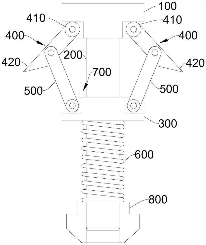
[0042] figure 1 Schematic diagram of the structure of the borehole stress gauge installation and free recovery locator provided by the first embodiment of the present invention. Please refer to figure 1 , the present embodiment provides a drilling stress gauge installation and free recovery positioner, which includes a base 100 , a guide post 200 , a sleeve 300 , a latch 400 , a support rod 500 , an elastic member 600 and a limit mechanism 700 .
[0043] Wherein, the guide column 200 is fixedly arranged on the base 100, the sleeve 300 is arranged around the outside of the guide column 200 and can move along the length direction of the guide column 200; 420, the hinged end 410 is hinged with the base 100, and the insertion end 420 is used to insert into the well wall; the two ends of the support rod 500 are respectively hinged with the middle part of the latch 400 and the sleeve 300; when the sleeve 300 moves toward the base 100 , the support rod 500 can push the insertion en...
no. 2 example
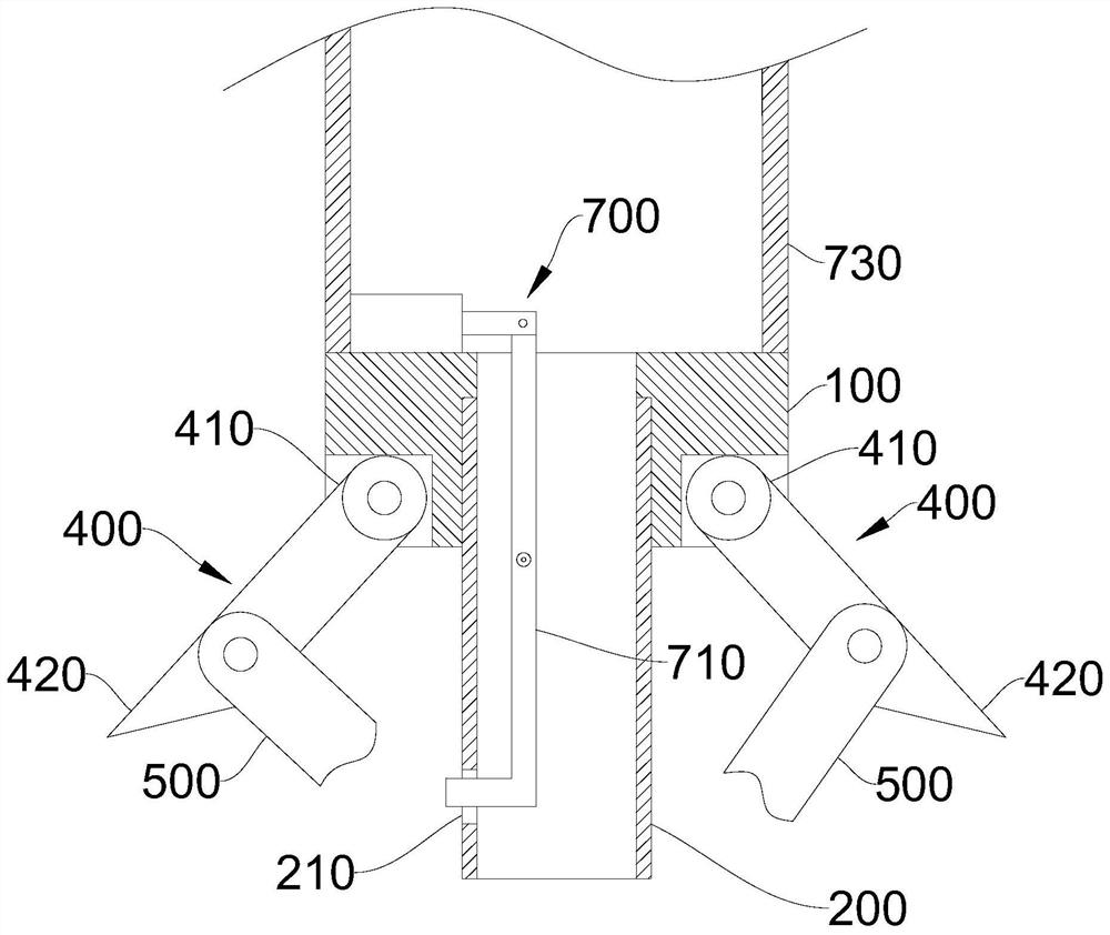
[0052] figure 2 A schematic diagram of the local structure of the first borehole stress gauge installation and free recovery locator provided in the second embodiment of the present invention; image 3 It is a schematic diagram of the partial structure of the second drilling stress gauge installation and free recovery positioner provided by the second embodiment of the present invention. Please refer to figure 2 , image 3 , this embodiment provides a borehole stress gauge installation and free recovery locator, which is roughly the same as the borehole stress gauge installation and free recovery locator of the first embodiment, the difference between the two is that the borehole stress gauge of this embodiment The limit mechanism 700 in the gauge installation and free recovery locator includes a swing rod 710; the guide post 200 is a hollow cylinder, and the side wall of the guide post 200 is provided with a through hole 210; the swing rod 710 is hinged on the inner wall ...
no. 3 example
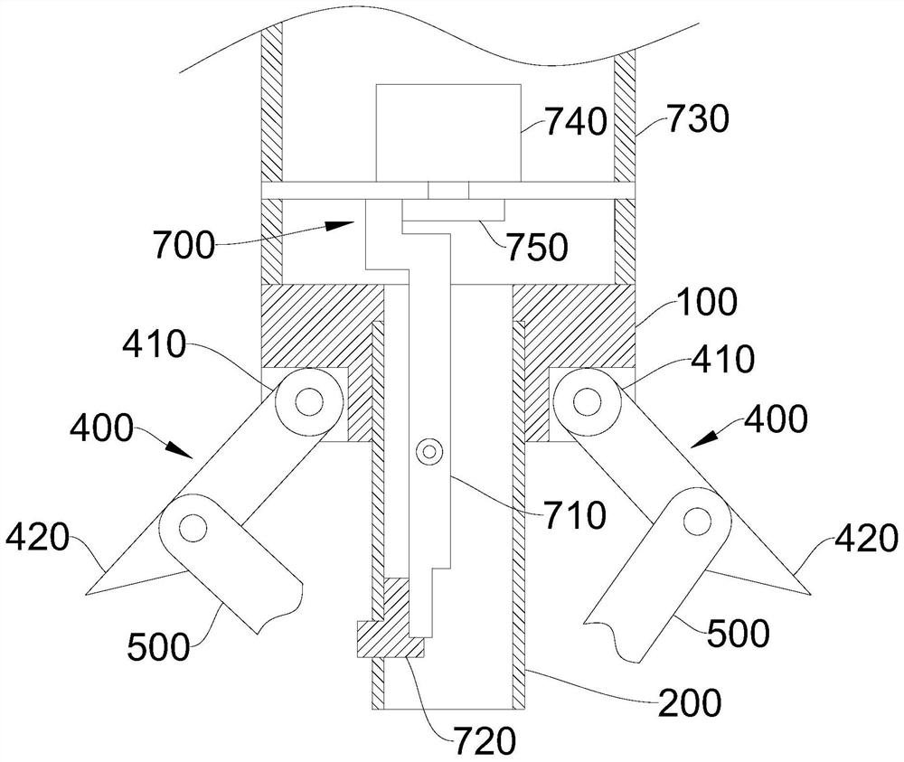
[0057] Figure 4 A schematic diagram of the partial structure of the borehole stress gauge installation and free recovery locator provided by the third embodiment of the present invention. Please refer to Figure 4 , this embodiment provides a borehole stress gauge installation and free recovery locator, which is roughly the same as the borehole stress gauge installation and free recovery locator of the second embodiment, the difference between the two lies in the borehole stress gauge installation and free recovery locator of the second embodiment. The driving device in the meter installation and free recovery positioner also includes a gear set 760 and a rotating rod 770; Connected, the eccentric wheel 750 is arranged on the rotating rod 770; the motor 740 drives the rotating rod 770 to rotate through the gear set 760, and the rotating rod 770 pushes the swing rod 710 to swing through the eccentric wheel 750.
[0058] On the basis of the second embodiment and the third emb...
PUM
 Abstract
Description
Claims
Application Information
 - R&D Engineer
- R&D Manager
- IP Professional
- Industry Leading Data Capabilities
- Powerful AI technology
- Patent DNA Extraction
Browse by: Latest US Patents, China's latest patents, Technical Efficacy Thesaurus, Application Domain, Technology Topic, Popular Technical Reports.
© 2024 PatSnap. All rights reserved.Legal|Privacy policy|Modern Slavery Act Transparency Statement|Sitemap|About US| Contact US: help@patsnap.com