Coupling agent coating equipment for manufacturing insulator for power transmission

A coupling agent and insulator technology, applied in the field of power transmission, can solve the problems of time-consuming and labor-intensive fixing process, inconvenient fixing of insulators, and damage to the health of workers. damage effect

Inactive Publication Date: 2021-02-19
陈鹏鹏
View PDF8 Cites 0 Cited by
  • Summary
  • Abstract
  • Description
  • Claims
  • Application Information

AI Technical Summary

Problems solved by technology

[0004] 1. It is inconvenient to fix the insulator, and the fixing process is time-consuming and laborious;
[0005] 2. When the staff takes out the insulator, they will touch the unsolidified coupling agent, which will affect the coating effect;
[0006] 3. The irritating smell emitted by the coupling agent will damage the health of the staff

Method used


Image

  • Coupling agent coating equipment for manufacturing insulator for power transmission
  • Coupling agent coating equipment for manufacturing insulator for power transmission
  • Coupling agent coating equipment for manufacturing insulator for power transmission

Examples


Embodiment 1

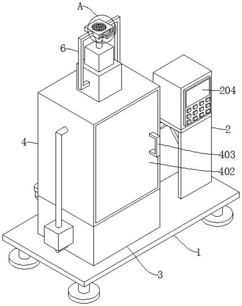
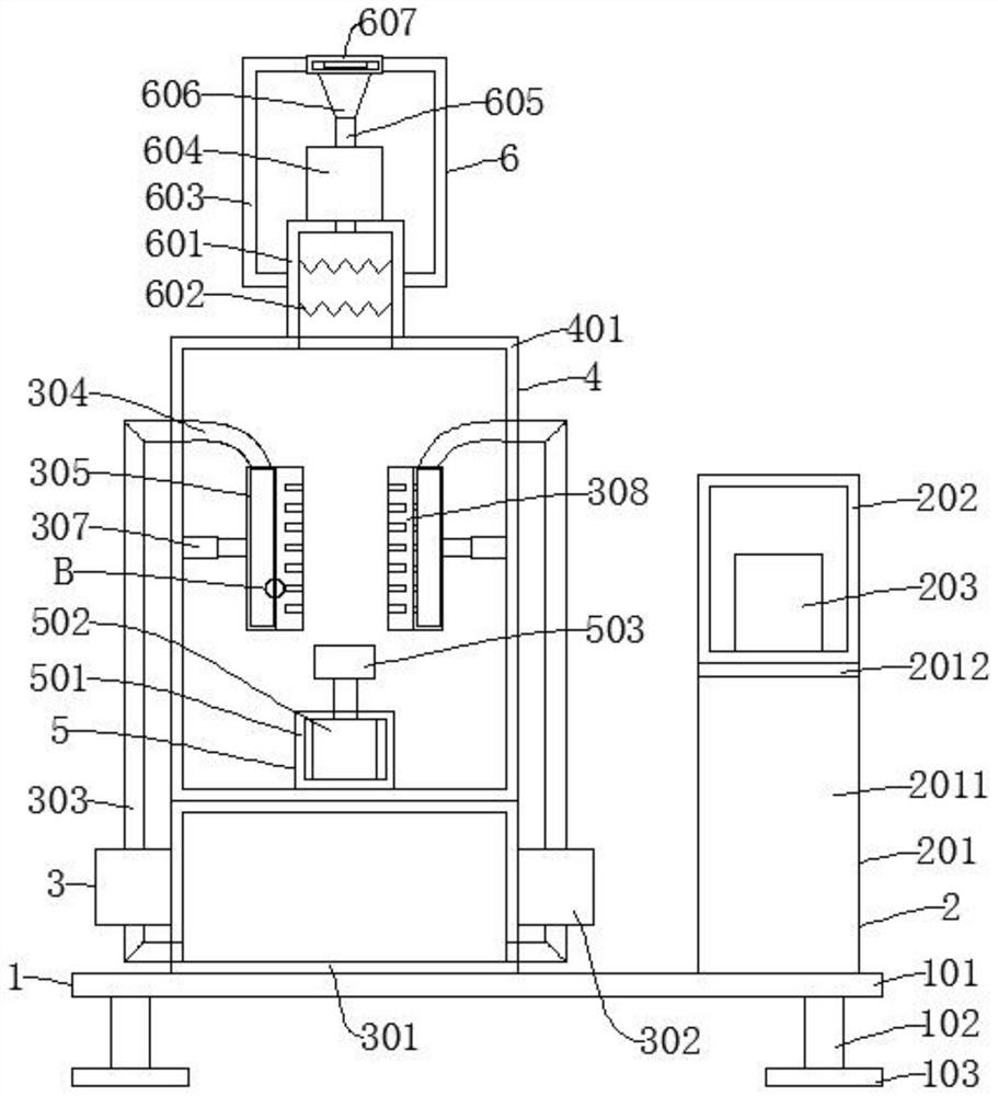
[0046] Such as figure 1 , image 3 , Figure 5 , Figure 7 , Figure 8 , Figure 9 As shown, a coupling agent coating equipment made of insulators for power transmission includes a support mechanism 1, a control mechanism 2 for controlling the operation of the device, a coating mechanism 3, and a closing mechanism 4. A control mechanism 2 is installed above the support mechanism 1 One side of the control mechanism 2 is provided with a coating mechanism 3, and a sealing mechanism 4 is fixed above the coating mechanism 3, and also includes a rotating mechanism 5, a drying mechanism 6, and a purification mechanism 7. The rotating mechanism 5 is installed inside the sealing mechanism 4, and the drying mechanism 6 is installed above the closing mechanism 4, and the purification mechanism 7 is fixed at the rear of the closing mechanism 4;

[0047] The support mechanism 1 includes a support plate 101, a support column 102, and a chassis 103. The support column 102 is installed b...

Embodiment 2

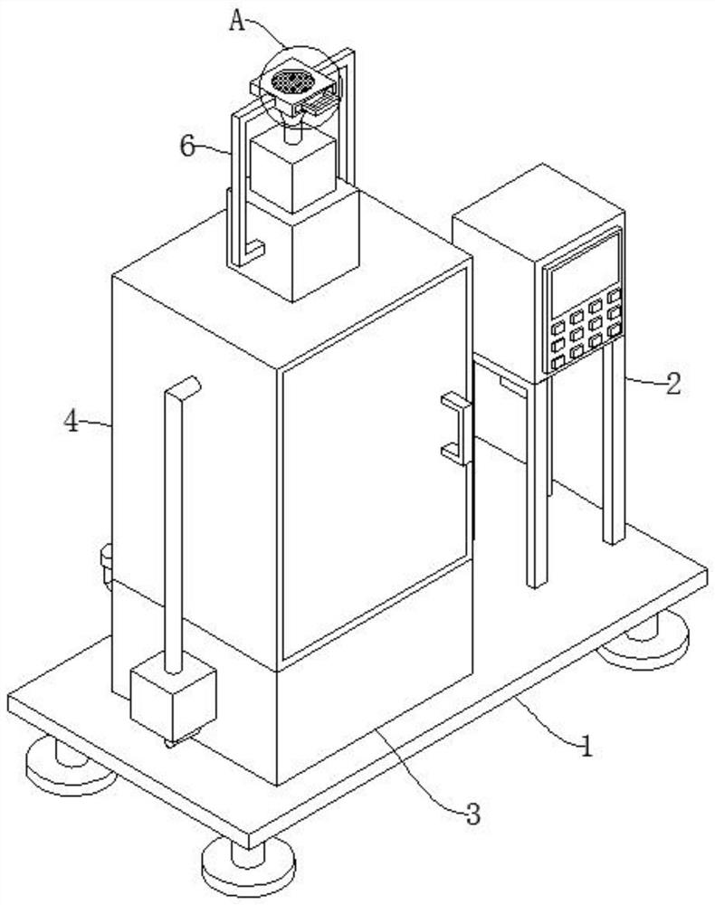
[0057] Such as figure 2 , Figure 4 , Figure 6 , Figure 7 , Figure 8 , Figure 9 As shown, the difference between Embodiment 2 and Embodiment 1 is that the vertical plate 2011, the horizontal plate 2012, and the inclined plate 2013 are replaced by the support frame 2014 and the first fixed frame 2015. During the operation of the device, the support frame 2014 and the first fixed frame A fixing frame 2015 works together to support and fix the control box 202 .


PUM


Abstract

The invention discloses coupling agent coating equipment for manufacturing an insulator for power transmission. The coupling agent coating equipment comprises a supporting mechanism, a control mechanism used for controlling operation of a device, a coating mechanism and a closing mechanism. Through the design of a rotating mechanism, a rotating cylinder, a spring and a clamping plate, a steel anchor of the insulator can be easily fixed, and the fixing process is simple and convenient; through the arrangement of a drying mechanism, gas is filtered through a dust filter screen, the filtered gasenters a heating box under the action of an air blower, the gas is heated through an electric heating wire, the high-temperature gas acts on the surface of the insulator so as to dry a coupling agent,the time required for drying the coupling agent is shortened, and meanwhile the situation that the coating effect is influenced due to the fact that a worker touches the unsolidified coupling agent can be avoided; and through the arrangement of a purification mechanism, an HEPA filter screen and an activated carbon adsorption layer can purify harmful gas generated in the coating process, and therefore the body health of workers is prevented from being damaged.

Description

technical field [0001] The invention relates to the technical field of power transmission, in particular to a coupling agent coating device for manufacturing insulators for power transmission. Background technique [0002] Insulators are special insulation controls that can play an important role in overhead transmission lines. In the early years, insulators were mostly used on utility poles, and gradually developed into a high-voltage wire connection tower with many disc-shaped insulators hanging on one end. It is used to increase the creepage distance, usually made of glass or ceramics, and is called an insulator. Insulators should not fail due to various electromechanical stresses caused by changes in the environment and electrical load conditions, otherwise the insulator will not play a significant role and will impair the service and operating life of the entire line. [0003] Insulators need to be coated with coupling agents on their surfaces during the manufacturing ...

Claims


Application Information

Patent Timeline
Patent Type & Authority Applications(China)
IPC IPC(8): B05C11/10B05C13/02B05C9/14B05C15/00B05D3/04H01B19/04B01D46/12B01D53/04
CPCB01D46/12B01D53/04B01D2253/102B05C9/14B05C11/10B05C11/1039B05C13/02B05C15/00B05D3/0413H01B19/04
Inventor 陈鹏鹏杨李强
Owner 陈鹏鹏
Why Eureka
Try Eureka