
Display panel and display device

A display panel and display area technology, which is applied in the direction of identification devices, instruments, TVs, etc., can solve the problems of poor display and large display differences in display areas, so as to improve the overall display effect, avoid uneven display, and improve display uniformity Effect

Active Publication Date: 2021-02-12
XIAMEN TIANMA MICRO ELECTRONICS
View PDF3 Cites 4 Cited by
  • Summary
  • Abstract
  • Description
  • Claims
  • Application Information

AI Technical Summary

Problems solved by technology

In order to improve the light transmittance of the semi-transparent area, the pixel density of the semi-transparent area is usually set to be small, resulting in a large display difference between the semi-transparent area and the conventional display area, and poor display is prone to occur

Method used


Image

  • Display panel and display device
  • Display panel and display device
  • Display panel and display device

Examples


Embodiment Construction

[0029] Various exemplary embodiments of the present invention will now be described in detail with reference to the accompanying drawings. It should be noted that the relative arrangements of components and steps, numerical expressions and numerical values ​​set forth in these embodiments do not limit the scope of the present invention unless specifically stated otherwise.

[0030] The following description of at least one exemplary embodiment is merely illustrative in nature and in no way taken as limiting the invention, its application or uses.

[0031] Techniques, methods and devices known to those of ordinary skill in the relevant art may not be discussed in detail, but where appropriate, such techniques, methods and devices should be considered part of the description.

[0032] In all examples shown and discussed herein, any specific values ​​should be construed as exemplary only, and not as limitations. Therefore, other instances of the exemplary embodiment may have dif...


PUM


Abstract

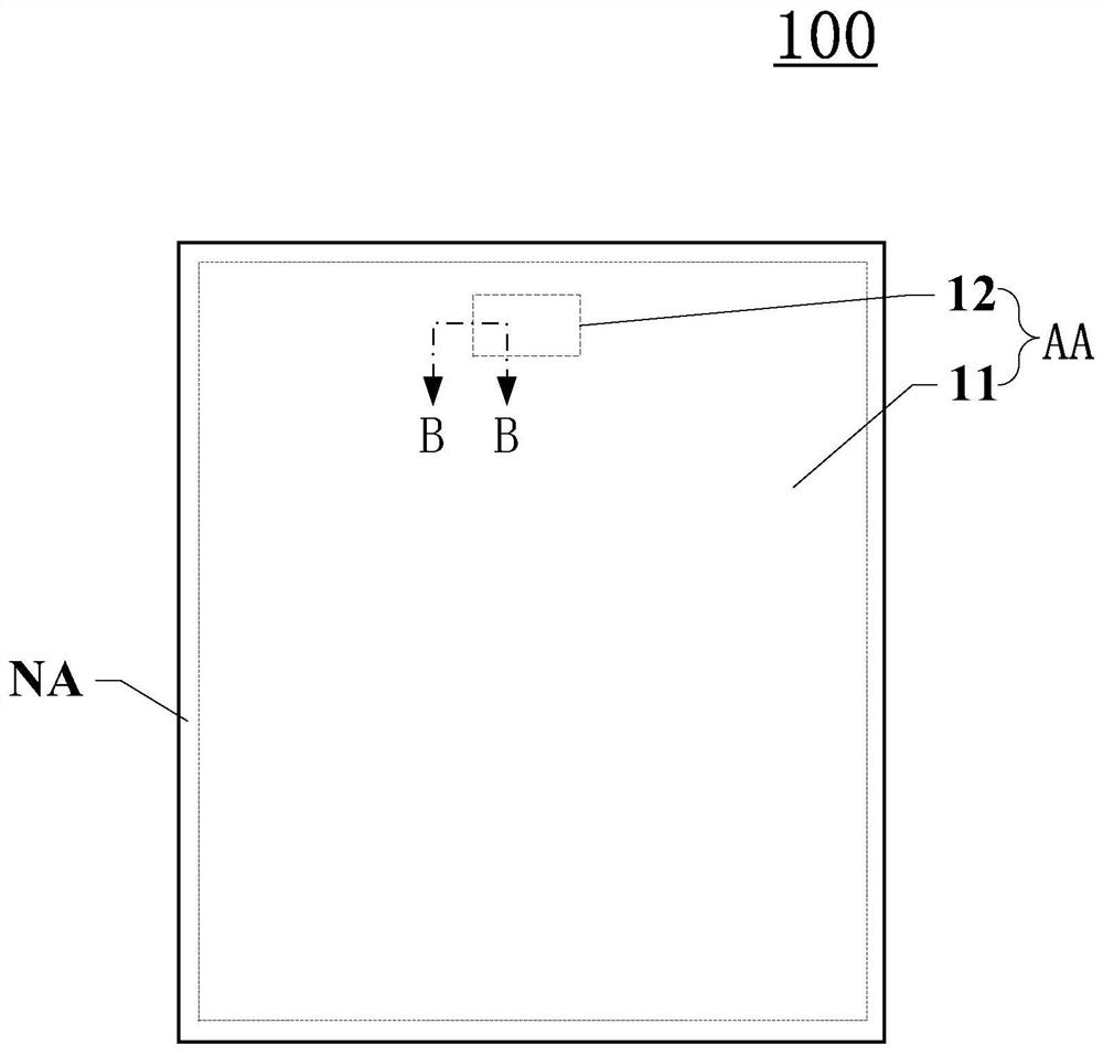
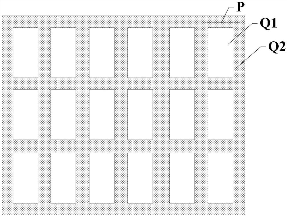
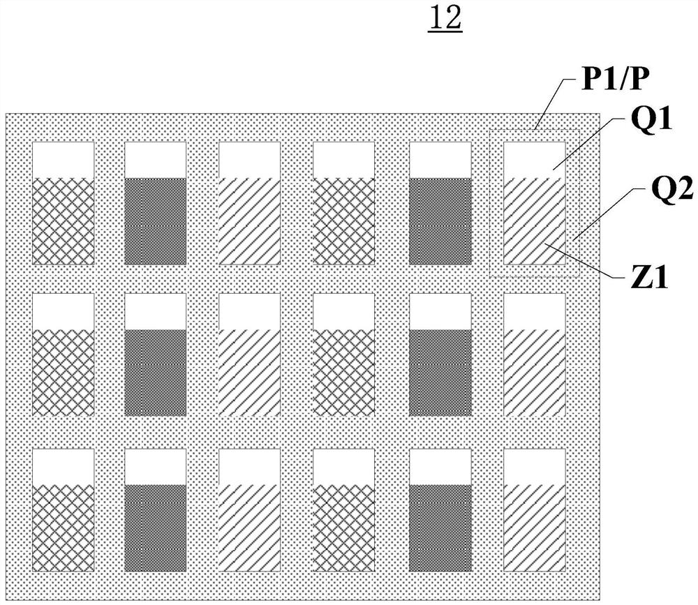
The invention discloses a display panel and a display device, and relates to the technical field of display, a display area comprises a conventional display area and a semi-transparent display area, and the pixel density of the semi-transparent display area is equal to the pixel density of the conventional display area; the display area comprises a plurality of sub-pixels, and each sub-pixel comprises a light-transmitting area and a non-light-transmitting area; the sub-pixels at least comprise color sub-pixels, each color sub-pixel comprises a color resistor of one color, and the color resistor is filled in the light-transmitting area; color sub-pixels in the semitransparent display area are first sub-pixels, and color resistors corresponding to the first sub-pixels are first color resistors; the color sub-pixel in the conventional display area is a second sub-pixel, and the color resistor corresponding to the second sub-pixel is a second color resistor; the area of the orthographic projection of at least one first color resistor on the light emitting surface of the display panel is S1, the area of the orthographic projection of any second color resistor on the light emitting surface is S2, and S1 is smaller than S2. Therefore, the display uniformity of the display panel and the display device can be improved.

Description

technical field [0001] The present invention relates to the field of display technology, and more specifically, to a display panel and a display device. Background technique [0002] With the development of display technology, display panels have higher and higher screen-to-body ratios, and full screens have attracted widespread attention due to their narrow-frame or even frame-less display effects. At present, display devices such as mobile phones and tablet computers often need to reserve space for electronic photosensitive devices such as commonly used front cameras, infrared sensing devices, and fingerprint recognition devices. For example, these photosensitive devices are arranged at the top of the front of the display device, and the corresponding position forms a non-display area, thereby reducing the screen-to-body ratio of the device. [0003] In the prior art, in order to increase the screen-to-body ratio, a high light transmission area may be provided in the disp...

Claims


Application Information

Patent Timeline
IPC IPC(8): G09F9/302G02F1/1335G02F1/1333H04N5/225
CPCG09F9/302G02F1/133514G02F1/13338H04N23/57
Inventor 李东华魏晓丽
Owner XIAMEN TIANMA MICRO ELECTRONICS
Learn More