Mechanical angle-adjustable heightening device based on constructional engineering

A kind of construction engineering and mechanical technology, which is applied in the direction of mechanical equipment, supporting machines, machine tables/supports, etc., can solve the problems of inability to quickly adjust the angle, the overall thickness of the heightening device, the complex structure and shape, and the inconvenience of large-scale transportation, etc., to achieve adjustment Convenience, stability and anti-slip effects

Active Publication Date: 2021-02-12
罗均羽 +1
View PDF5 Cites 0 Cited by
  • Summary
  • Abstract
  • Description
  • Claims
  • Application Information

AI Technical Summary

Problems solved by technology

[0007] The purpose of the present invention is to provide a mechanical adjustable angle raising device based on construction engineering to solve the problem that the currently used raising device proposed in the above background technology is thicker overall, which is not conducive to quickly and conveniently adjusting machinery or equipment. The height of the pad cannot be adjusted quickly after the pad is raised. The complex shape of the structure is inconvenient to transport in large quantities, which is not conducive to the stable use of construction projects.

Method used


Image

  • Mechanical angle-adjustable heightening device based on constructional engineering
  • Mechanical angle-adjustable heightening device based on constructional engineering
  • Mechanical angle-adjustable heightening device based on constructional engineering

Examples


Embodiment Construction

[0031] The following will clearly and completely describe the technical solutions in the embodiments of the present invention with reference to the accompanying drawings in the embodiments of the present invention. Obviously, the described embodiments are only some of the embodiments of the present invention, not all of them.

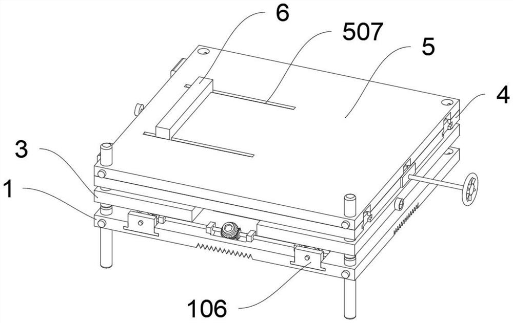
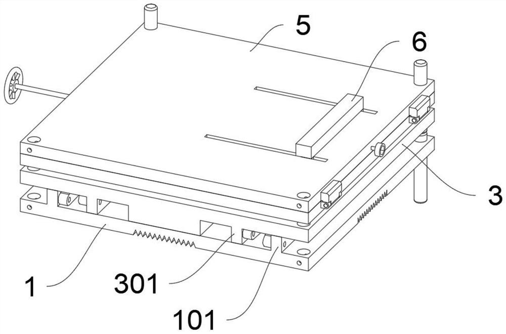
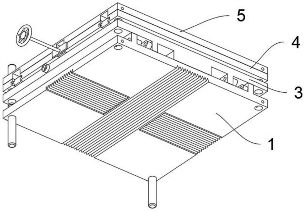
[0032] see Figure 1 to Figure 8, an embodiment provided by the present invention: a mechanical adjustable angle raising device based on construction engineering, including a pedestal 1 and a lifting plate 3; wherein, the pedestal 1 also includes a cushion strip 101, a chute 102 , a driven shaft 103, a transmission shaft 104; two sets of pads 101 are integrally arranged on both sides of the top of the pedestal 1; a chute 102 is provided in the middle of the rear top of the pedestal 1; the middle of the inclined surface of the chute 102 is rotated by a bearing A transmission shaft 104 is provided, and the outer end of the transmission shaft 104 is an inn...


PUM


Abstract

The invention discloses a mechanical angle-adjustable heightening device used based on constructional engineering, relates to the technical field of constructional engineering, and solves the problemsthat a currently used heightening device is relatively thick as a whole, is not beneficial to quickly and conveniently heightening a machine or equipment and cannot quickly adjust an angle after heightening. The mechanical angle-adjustable heightening device based on the constructional engineering comprises a pedestal and a lifting plate; the pedestal further comprises a sliding groove, check blocks and lead screws A; two sets of sliding grooves are arranged at the top of the rear side of the pedestal; the check blocks are fixedly arranged at the rear ends of the sliding grooves; and the leadscrews A are rotatably arranged between the sliding grooves and the check blocks; and by arranging a transmission shaft, a driven shaft, the lead screws A and nut blocks, the lifting plate can be rapidly lifted in parallel through a connecting rod, a connecting rod A and a connecting rod B to be heightened, the device can bear the bottoms of supporting legs of mechanical equipment or tools, the whole device is of a four-side structure, large-scale conveying and carrying are facilitated, and stable use in the constructional engineering is facilitated.

Description

technical field [0001] The invention relates to the technical field of construction engineering, in particular to a mechanical adjustable angle heightening device used in construction engineering. Background technique [0002] Building construction refers to the production activities in the implementation stage of engineering construction. It is the construction process of various buildings. In the process of building construction, due to the uneven ground, it is often necessary to use pads to increase the balance of equipment or tools, place equipment or Tool toppled or tipped over. [0003] After searching, for example, the patent No. CN207017627U discloses a kind of raising device for building construction, including a vertical pipe, the top of the vertical pipe is provided with a jack supported at the bottom of the scaffold, and the bottom of the vertical pipe is provided with a threaded hole, a screw rod is arranged at the lower end of the vertical pipe, a block is arr...

Claims


Application Information

Patent Timeline
IPC IPC(8): F16M11/04F16M11/10F16M11/18F16M11/38
CPCF16M11/04F16M11/10F16M11/18F16M11/38
Inventor 郑丽丽
Owner 罗均羽
Why Eureka
Try Eureka