
Cast steel supporting roller and preparation method thereof

A roll and cast steel technology, which is applied in the field of cast steel support roll and its preparation, can solve the problems of no auxiliary support structure, large force on the grabbing device, and low work efficiency, so as to solve the problem of inconvenient grabbing and reduce suction Intensity, the effect of improving work efficiency

Active Publication Date: 2021-02-12
铜陵市大明玛钢有限责任公司
View PDF7 Cites 0 Cited by
  • Summary
  • Abstract
  • Description
  • Claims
  • Application Information

AI Technical Summary

Problems solved by technology

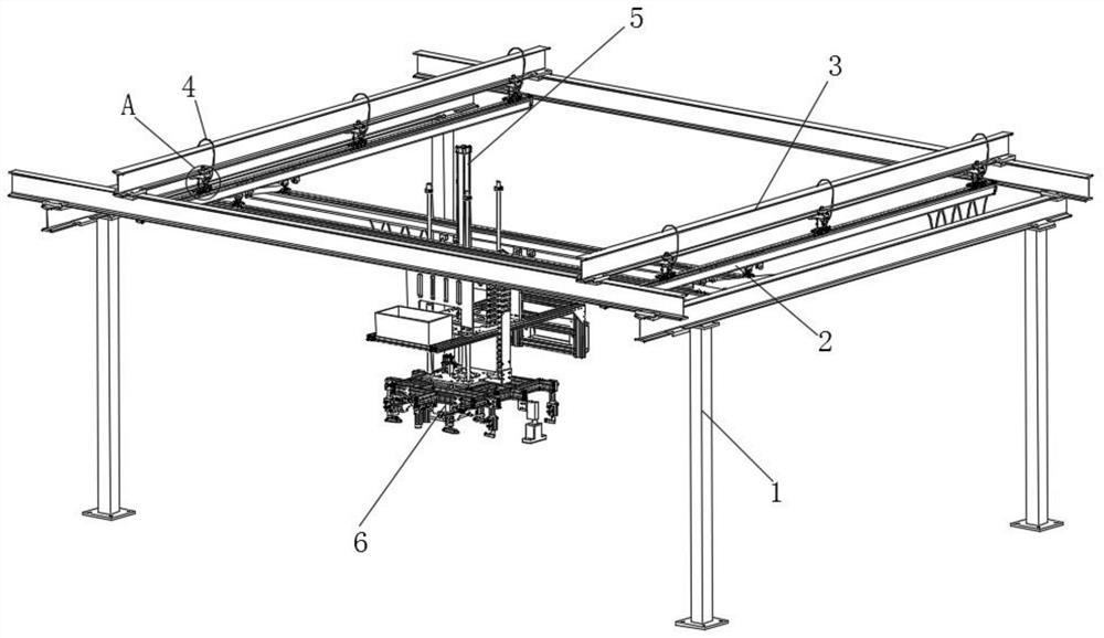
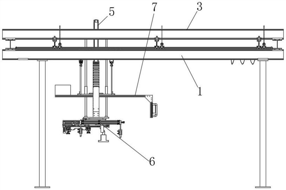
[0004] The object of the present invention is to provide a cast steel back-up roll and its preparation method to solve the problem that the base of the grab device cannot be in the In a horizontal state, it is inconvenient for the four suction cups to contact the surface of the main body of the roll, it is inconvenient to absorb the main body of the fixed roll, and the purpose of handling cannot be realized; in the preparation process of the existing cast steel support roll, the roll is directly grasped only by the grasping device, and the The force of the taking device is too large, there is no auxiliary support structure, and the suction force of the suction cup on the main body of the roll cannot be reduced, and the roll is easy to fall off, which is not convenient for the fixing work of the roll; during the preparation process of the existing cast steel support roll, the grabbing device The movement remains unchanged, or only one-way movement is possible, requiring manual handling, a large amount of labor, and low work efficiency

Method used


Image

  • Cast steel supporting roller and preparation method thereof
  • Cast steel supporting roller and preparation method thereof
  • Cast steel supporting roller and preparation method thereof

Examples


Embodiment Construction

[0036] The technical solutions of the present invention will be clearly and completely described below in conjunction with the embodiments. Apparently, the described embodiments are only some of the embodiments of the present invention, not all of them. Based on the embodiments of the present invention, all other embodiments obtained by persons of ordinary skill in the art without creative efforts fall within the protection scope of the present invention.

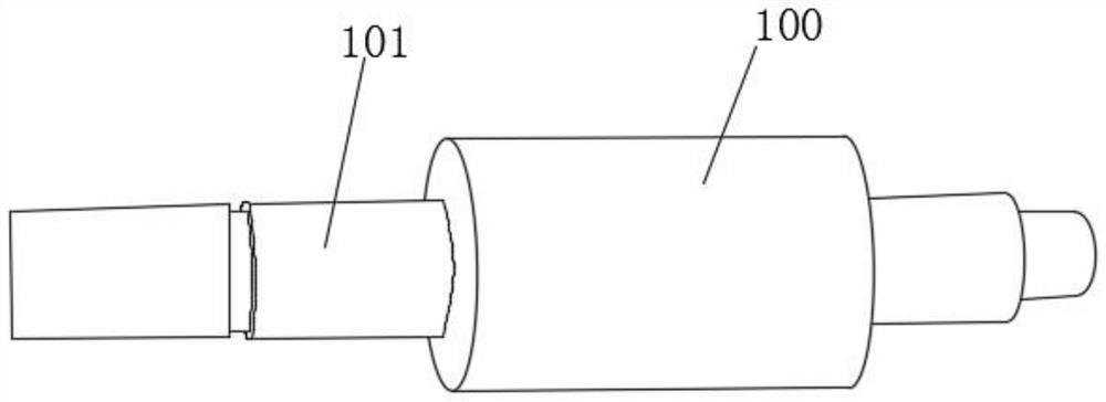
[0037] Such as Figure 1-7 As shown, a cast steel support roll includes a roll main body 100 and a roll end shaft 101, and roll end shafts 101 are respectively arranged on the side walls at both ends of the roll main body 100;

[0038] The cast steel backup roll is made by the following process:

[0039] First, the roll main body 100 and the roll end shaft 101 are smelted separately, and the roll main body 100 and the roll end shaft 101 are fused into one by using a horizontal centrifugal casting process. The shaped roll i...


PUM


Abstract

The invention discloses a cast steel supporting roller which comprises a roller main body and roller end shafts, wherein the roller end shafts are arranged on the side walls of two ends of the rollermain body correspondingly. The cast steel supporting roller is prepared by the following processes: first, smelting the roller main body and the roller end shafts separately; melting the roller main body and the roller end shafts integrally by using a horizontal centrifugal casting process; controlling a lifting plate to move upward, wherein the roller is separated from the ground; pushing a handrail, wherein a fixed plate moves along two transverse supporting rods through supporting rollers on two side plates; forming chutes in the bottoms of two first slide rails; arranging a plurality of pulleys on the tops of two triangular plates; arranging the pulleys in the chutes; pushing the two transverse supporting rods to move along the two first slide rails to achieve a longitudinal moving purpose of a grabbing device; and moving the roller to a next step position, wherein it is convenient for the roller to move. Manual transportation is not needed, the labor amount is reduced and the workefficiency is improved.

Description

technical field [0001] The invention relates to the technical field of roll preparation, in particular to a cast steel support roll and a preparation method thereof. Background technique [0002] Cast steel rolls are cheaper to manufacture than forged steel rolls. When the heat treatment system is the same, the wear resistance of cast steel rolls is better than that of forged steel rolls with the same composition, but the toughness is lower. Composite casting can significantly improve the strength and toughness of the cast steel back-up roll core and roll neck. The production of cast steel rolls includes processes such as smelting, casting, heat treatment, machining and testing, but there is a problem of inconvenient movement of the rolls during preparation. [0003] During the preparation process of the existing cast steel backup roll, when the roll is grabbed by the traditional grabbing device, the base of the grabbing device cannot be in a horizontal state, and it is no...

Claims


Application Information

Patent Timeline
IPC IPC(8): B25J5/02B25J15/06B65G47/91B21B27/02B22D13/00B22D19/00
CPCB25J5/02B22D13/00B22D19/00B21B27/02B25J15/0683B65G47/918
Inventor 章成希夏章霞张剑
Owner 铜陵市大明玛钢有限责任公司
Learn More