Trunk fixing device for radiotherapy department treatment
A fixing device and torso technology, applied in the medical field, can solve problems such as small application range and inability to adjust angles
- Summary
- Abstract
- Description
- Claims
- Application Information
AI Technical Summary
Problems solved by technology
Method used
Image


Examples
specific Embodiment approach 1
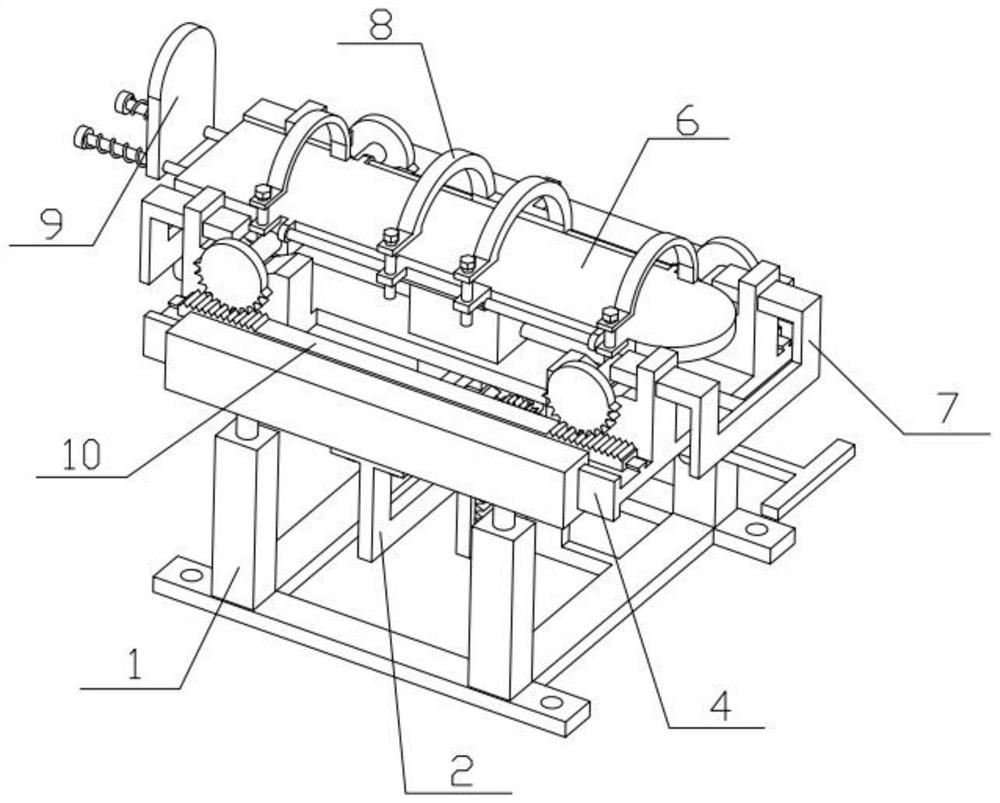
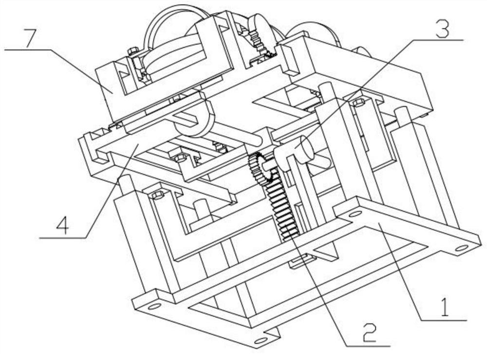
[0038] Combine below Figure 1-13 Describe this embodiment, a torso immobilization device during radiotherapy treatment, including a chassis mechanism 1, a rack transmission mechanism 2, a gear transmission mechanism 3, a support table mechanism 4, a transmission mechanism 5, a trunk support mechanism 6, and a rotation limiting mechanism 7. Trunk fixing mechanism 8, pedal mechanism 9 and transmission rack 10, the rack transmission mechanism 2 is connected to the middle part of the chassis mechanism 1, the gear transmission mechanism 3 is connected on the chassis mechanism 1, and the gear transmission mechanism 3 is located at The left part of the rack transmission mechanism 2, the support platform mechanism 4 is connected to the top of the underframe mechanism 1, and the front and rear sides of the support platform mechanism 4 are all slidably connected with the transmission rack 10, and the transmission mechanism 5 is connected to the bottom of the support platform mechanism 4...
specific Embodiment approach 2
[0040] Combine below Figure 1-13 Describe this embodiment, this embodiment will further explain Embodiment 1, the underframe mechanism 1 includes a support base plate 101, a hollow column 102, a sliding column 103, a connecting plate 104, a chute 105 and a motor support plate 106, and supports The four corners of the bottom plate 101 are fixedly connected with hollow columns 102, and each hollow column 102 is slidably connected with a sliding column 103, and the connecting plate 104 at the front is fixedly connected with the two sliding columns 103 at the front. The connecting plate 104 at the rear is fixedly connected to the two sliding posts 103 at the rear, each connecting plate 104 is provided with a chute 105 , and the motor supporting plate 106 is fixedly connected to the right side of the supporting base plate 101 . The height position of the connecting plate 104 can be adjusted by sliding up and down of the sliding column 103 in the hollow column 102. The function of ...
specific Embodiment approach 3
[0042] Combine below Figure 1-13 Describe this embodiment, this embodiment will further explain Embodiment 2, the rack gear 2 includes a rack 201, an L-shaped connecting plate 202 and a bolt 203, and the left and right ends of the rack 201 are fixedly connected with The L-shaped connecting plate 202 is threaded with two bolts 203 at the upper end of each L-shaped connecting plate 202, and the L-shaped connecting plate 202 on the left side is screwed to the connection at the rear by the two bolts 203 on it. At the bottom of the plate 104, the L-shaped connecting plate 202 on the right is screwed to the bottom of the connecting plate 104 at the front through two bolts 203 thereon. Due to the meshing transmission between the transmission gear 302 and the rack 201, when the gear 302 rotates, it will drive the rack 201 to move upward, and the rack 201 will drive the connecting plate 104 to move upward through the L-shaped connecting plates 202 at both ends to adjust If the height...
PUM
 Abstract
Description
Claims
Application Information
 - Generate Ideas
- Intellectual Property
- Life Sciences
- Materials
- Tech Scout
- Unparalleled Data Quality
- Higher Quality Content
- 60% Fewer Hallucinations
Browse by: Latest US Patents, China's latest patents, Technical Efficacy Thesaurus, Application Domain, Technology Topic, Popular Technical Reports.
© 2025 PatSnap. All rights reserved.Legal|Privacy policy|Modern Slavery Act Transparency Statement|Sitemap|About US| Contact US: help@patsnap.com