Planting frame with drainage channel
A drainage channel and planting frame technology, which is applied in the field of planting frames with drainage channels, can solve the problems of inability to achieve convenient drainage, achieve the effects of increasing strength, slowing down soil erosion, and reducing processing procedures
- Summary
- Abstract
- Description
- Claims
- Application Information
AI Technical Summary
Problems solved by technology
Method used
Image

Examples
Embodiment 1
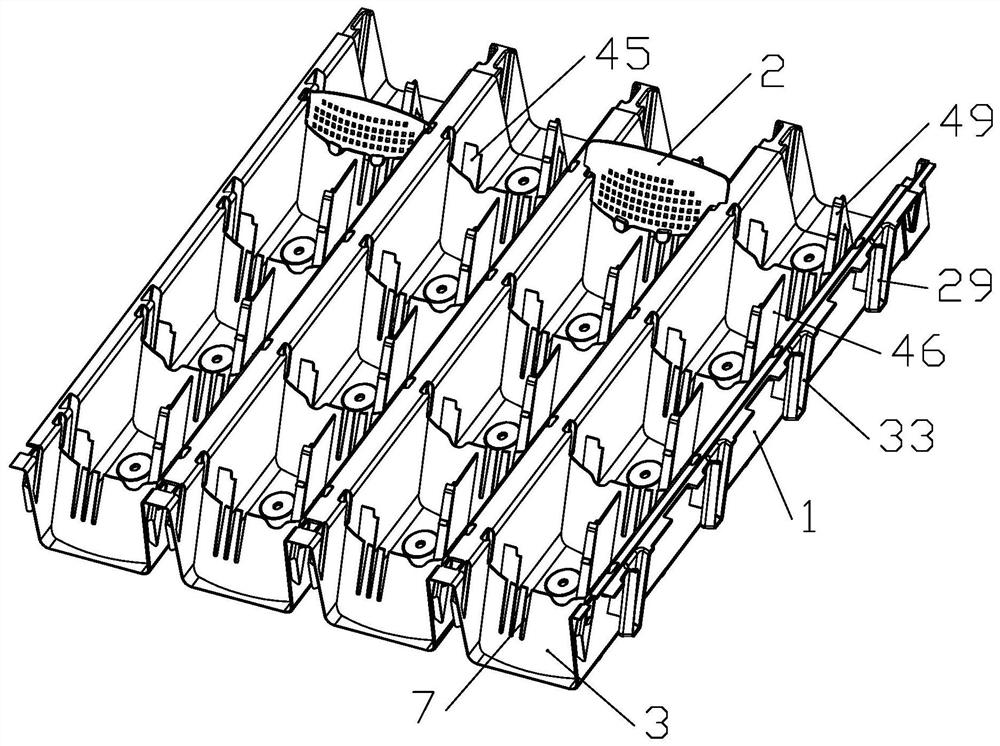
[0043] combine Figure 1-Figure 3 , it can be seen that a planting frame with a drainage channel includes a main body 1, and the main body 1 is provided with several planting grooves 5 for placing plants, and the planting groove 5 is built with partitions for dividing the planting groove 5 into several planting areas. Board II 3.
[0044] And the second partition 3 is provided with a drainage port 7, and the drainage port 7 is used to discharge the accumulated water in the current planting area to the next planting area. Therefore, while water and soil loss is slowed down by the dividing plate 2 3, water can also flow from the outlet to the next planting area, that is, water and soil loss can be slowed down while realizing drainage convenience.
[0045] And in the length direction of the main body 1, the drain outlets 7 of the two adjacent partitions 3 are located on different sides, thereby forming an "S" shaped drain channel.
[0046] Therefore when water flows from top to...
Embodiment 2
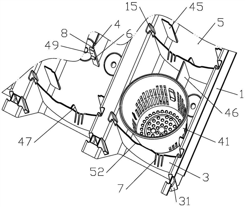
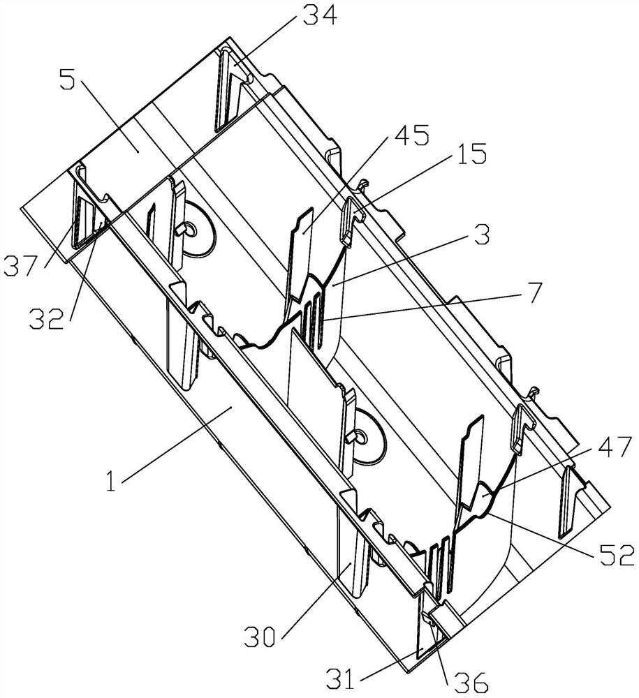
[0076] Embodiment 2: This embodiment is basically the same as Embodiment 1, the difference is that: a partition 2 is added, and the specific structure is as follows: figure 1 , Figure 4 and Figure 5 As shown, a partition one 2 is hung on the partition two 3, and at the same time, both side walls of the planting groove 5 are provided with connection grooves 15, and both sides of the partition one 2 are clamped in the connection groove 15.
[0077] Simultaneously the structure of dividing plate-2 is various, can be solid or offer several holes 54 for ventilating and water passage at dividing plate-2, and when dividing plate-2 is solid time, be used for the hole 54 of passing water The hole will be arranged on the main body 1 such as the overflow groove 52, so as to make the water flow up and down.
[0078] At the same time, the connection groove 15 is L-shaped, and the partition 12 is provided with a raised strip 16, and the convex strip 16 and the side of the partition 12 a...
Embodiment 3
[0081] Embodiment 3: This embodiment is basically the same as Embodiment 1, the difference is: the structure of the left and right connection of the main body 1: First, a connecting piece 55 is extended on one side of the main body 1, and the connecting piece 55 is bent to form a limiting plate 56 , and an overlapping slot 57 is formed between the limiting plate 56 and the main body 1 . Moreover, due to the existence of the overlapping slots 57 , the main bodies 1 are not completely abutted against each other, thereby providing space for the connection between the main bodies 1 .
[0082] Therefore, in actual use, when several main bodies 1 are spliced horizontally sequentially, the inner wall of the previous main body 1 away from the connecting piece 1 55 abuts against the inner wall of the limiting plate 56 of the latter main body 1 .
[0083] Therefore, the side support can be realized through the left and right connection, thereby ensuring the stability of the planting w...
PUM
 Abstract
Description
Claims
Application Information
 - R&D
- Intellectual Property
- Life Sciences
- Materials
- Tech Scout
- Unparalleled Data Quality
- Higher Quality Content
- 60% Fewer Hallucinations
Browse by: Latest US Patents, China's latest patents, Technical Efficacy Thesaurus, Application Domain, Technology Topic, Popular Technical Reports.
© 2025 PatSnap. All rights reserved.Legal|Privacy policy|Modern Slavery Act Transparency Statement|Sitemap|About US| Contact US: help@patsnap.com