
Road flatness detection method

A detection method and flatness technology, applied in the field of road detection and road flatness detection, can solve the problems of inability to monitor the road surface flatness in real time, and inability to detect road deformation, and achieve the effect of low cost.

Active Publication Date: 2021-02-09
宁夏公路工程质量检测中心(有限公司)
View PDF9 Cites 0 Cited by
  • Summary
  • Abstract
  • Description
  • Claims
  • Application Information

AI Technical Summary

Problems solved by technology

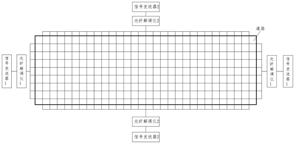
[0008] The purpose of the present invention is to: address the above existing problems, to provide a road smoothness detection method, by laying optical fibers in the road, real-time detection of light reflection in the optical fiber to judge the change of the road surface roughness, and the initial database Comparing and judging, accurately finding the road surface deformation point / area can solve the problem of accurate flatness detection of the road surface; it also solves the problem that the road surface flatness cannot be monitored in real time; it also solves the problem that the curved / curved road cannot be detected The problem of detecting whether deformation occurs

Method used


Image

  • Road flatness detection method
  • Road flatness detection method

Examples


Embodiment Construction

[0030] All features disclosed in this specification, or steps in all methods or processes disclosed, may be combined in any manner, except for mutually exclusive features and / or steps.

[0031] Any feature disclosed in this specification (including any appended claims, abstract), unless otherwise stated, may be replaced by alternative features which are equivalent or serve a similar purpose. That is, unless expressly stated otherwise, each feature is one example only of a series of equivalent or similar features.

[0032] Road roughness detection method of the present invention, comprises the following steps:

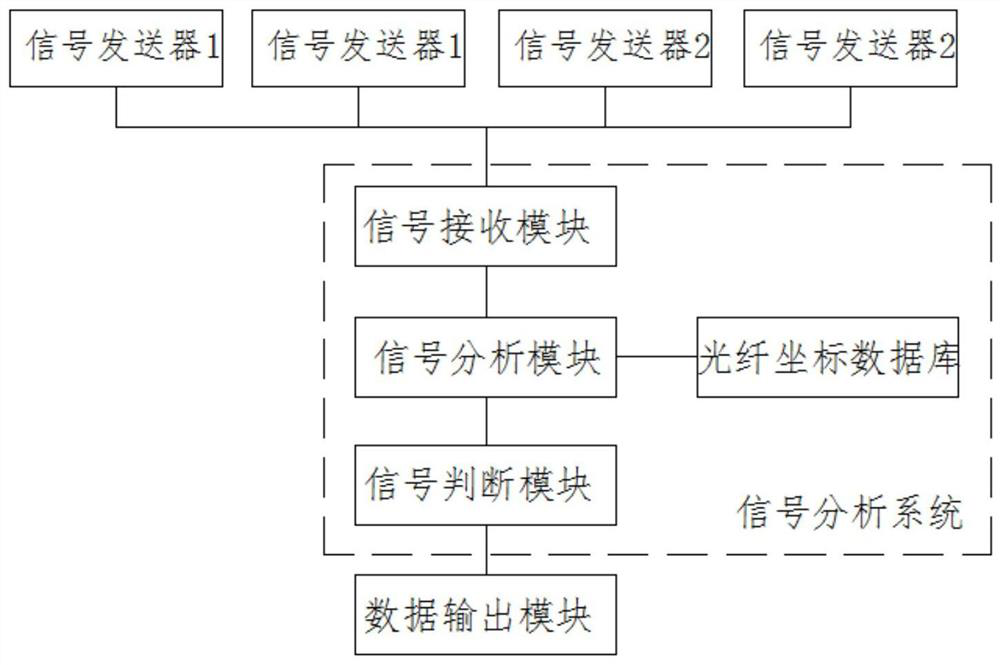
[0033] Signal collection steps: transmit and receive spectral signals to the optical fiber through the optical fiber mediator; the optical fiber mediator 1 is connected to the horizontally arranged optical fiber, and the horizontal spectral signal is sent to the signal transmitter 1; the optical fiber mediator 2 is connected to the vertically arranged optical fiber, Se...


PUM


Abstract

The invention discloses a road flatness detection method, and belongs to the field of road detection. The method comprises the following steps: a signal collection step: transmitting and receiving a spectral signal to an optical fiber through an optical fiber demodulator; a coordinate conversion step: enabling the spectral signal to correspond to an optical fiber label, and converting the spectralsignal into an optical fiber label signal; a signal analysis step: comparing and analyzing the optical fiber label signal and the optical fiber coordinate value, and finding out a deformation coordinate value with a difference point; a signal judgment step: judging whether the deformation coordinates can be connected with a forming variable region or not based on the condition of the deformationcoordinate values, if so, omitting a middle point and reserving edge points, and sequentially connecting to form a polygonal deformation region, and if not, judging as a deformation point; and an image display step: displaying the deformation area / deformation point in the initial optical fiber coordinate system in real time. According to the invention, the optical fiber is laid in the road, changeof the road surface flatness is judged by detecting the light reflection condition in the optical fiber in real time, and the road surface deformation point / area is accurately found.

Description

technical field [0001] The invention relates to the technical field of road detection, in particular to the technical field of road roughness detection. Background technique [0002] After the road paving is completed, due to terrain settlement, deformation, rain erosion, vehicle driving, heavy rolling, etc., it is easy to cause deformation of the roadside, forming pits or bulges, etc., causing road deformation, which in turn affects the safety of road driving , especially roads such as airport runways, racing tracks, and experimental roads, have extremely high requirements for the smoothness of the road; therefore, it is necessary to test the smoothness of the road for a long time. [0003] At present, the methods of road roughness detection include: [0004] 1. The traditional 3M ruler detection method is to place a 3-meter-long ruler on the road and check the fit between the ruler and the road surface to judge the smoothness of the road surface. This method can only jud...

Claims


Application Information

Patent Timeline
Patent Type & Authority Applications(China)
IPC IPC(8): E01C23/01
CPCE01C23/01
Inventor 不公告发明人
Owner 宁夏公路工程质量检测中心(有限公司)
Learn More