Pump components, compressors and air conditioners

A component and pump body technology, applied in pump components, machines/engines, liquid fuel engines, etc., can solve problems such as axial unbalanced overturning moment, refrigerant leakage, and detachment, so as to reduce the noise of the whole machine, improve reliability, The effect of improving the performance of the whole machine

Active Publication Date: 2021-10-15
GREE ELECTRIC APPLIANCES INC
View PDF17 Cites 0 Cited by
  • Summary
  • Abstract
  • Description
  • Claims
  • Application Information

AI Technical Summary

Problems solved by technology

[0002] The cavity of the sliding vane compressor is surrounded by the sliding vane, the main shaft, the cylinder, and the end faces of the upper and lower flanges. With the rotation of the main shaft and the sliding vane, when the sliding vane crosses the suction end angle, the suction of the front cavity ends. , start to compress, and become a compression chamber, then the main shaft continues to rotate, and the pressure inside the compression chamber rises. When the pressure reaches the discharge pressure, the valve opens, the compressor is in the exhaust state, and the slide continues to rotate. When the exhaust port is open, the valve plate is still in the exhaust state of opening or about to close. The position where the slide plate is covered by the exhaust port will receive an instantaneous axial gas force, and the exhaust port is close to the slide plate due to structural problems. The position of the head, which causes the sliding vane to generate an axially unbalanced overturning moment at this time, causing the sliding vane to suddenly tilt and instantly separate from the inner wall of the cylinder or the end face of the flange, resulting in refrigerant leakage

Method used


Image

  • Pump components, compressors and air conditioners
  • Pump components, compressors and air conditioners
  • Pump components, compressors and air conditioners

Examples


Embodiment Construction

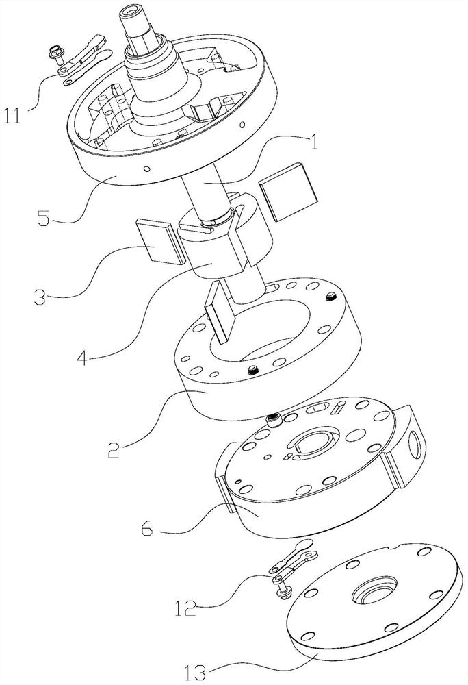
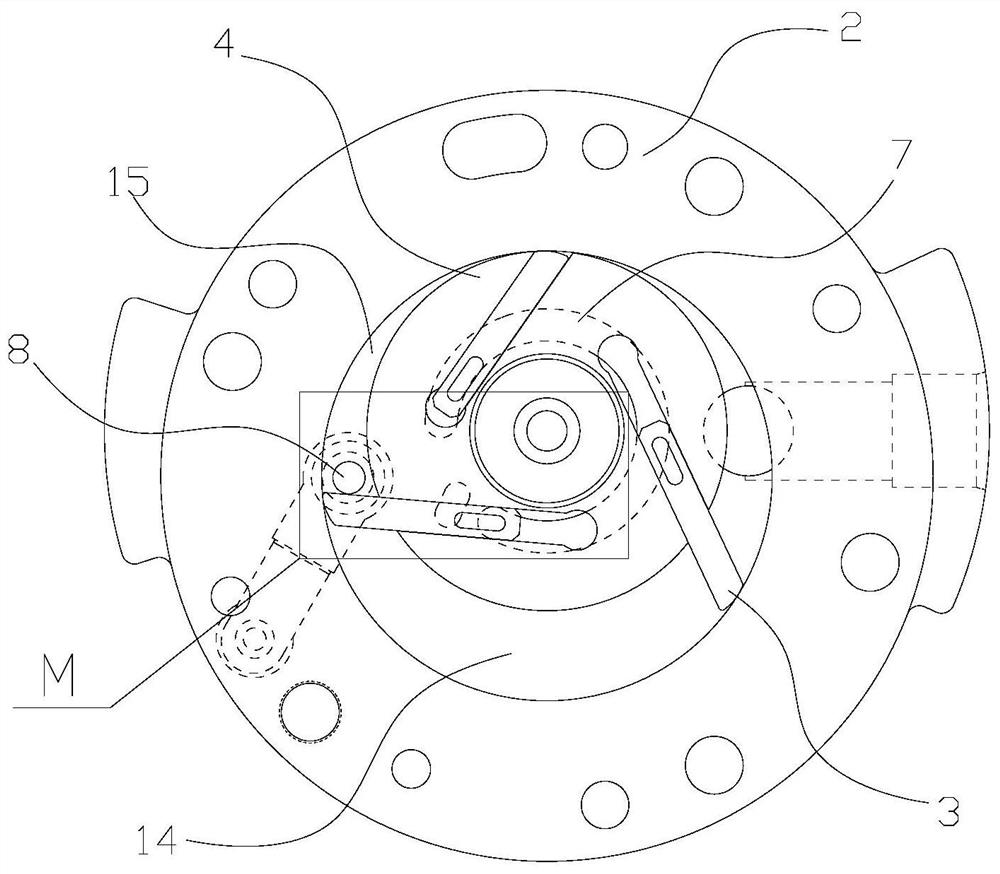
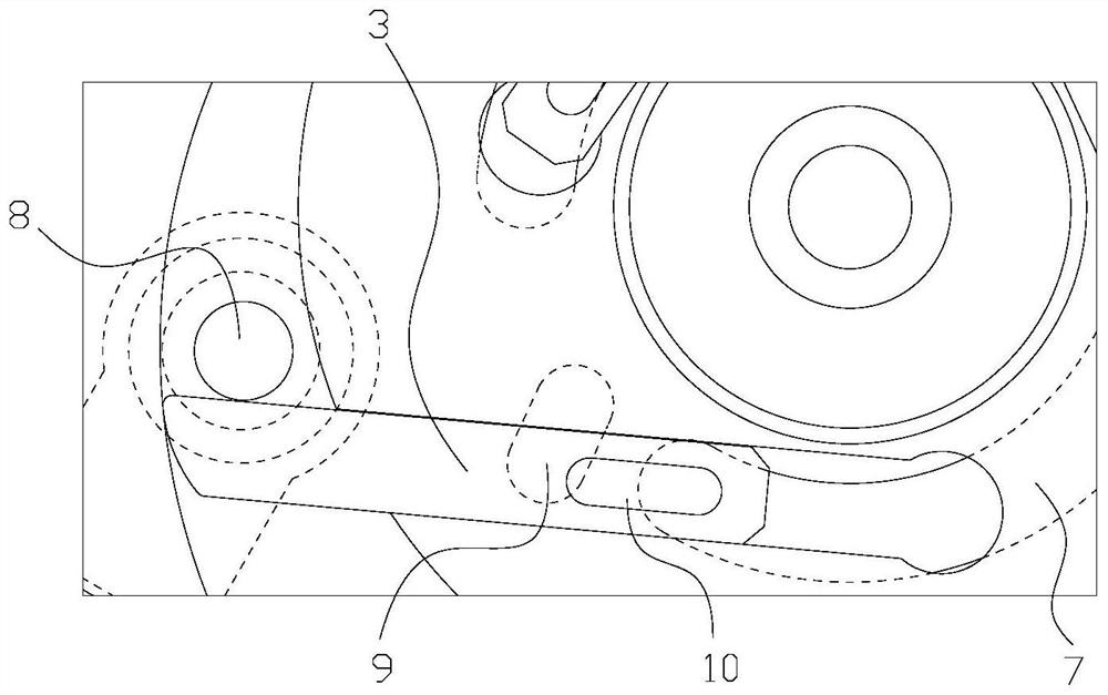
[0037] see in conjunction Figure 1 to Figure 14 As shown, according to the embodiment of the present application, the pump body assembly includes a main shaft 1, a flange, a cylinder 2 and a sliding piece 3, the main shaft 1 includes a convex portion 4, and a plurality of sliding pieces 3 are arranged on the convex portion 4 at intervals along the circumferential direction, The flange is provided with a back pressure oil groove and an exhaust port, and a pressure balance groove is also arranged on the flange. The pressure balance groove can communicate with the back pressure oil groove when the slide plate 3 moves to the position of the exhaust port, and when the slide plate 3 moves away from One side of the exhaust port exerts an axial force to balance the moment that the sliding vane 3 receives at the exhaust port.

[0038] During the working process of the pump body assembly, when the sliding vane 3 slides to the position of the exhaust port, it will be subjected to the ax...


PUM


Abstract

The application provides a pump body assembly, a compressor and an air conditioner. The pump body assembly includes a main shaft (1), a flange, a cylinder (2) and a sliding vane (3), the main shaft (1) includes a convex portion (4), and a plurality of sliding vanes (3) are arranged at intervals along the circumferential direction on the convex portion (4), the flange is provided with a back pressure oil groove and an exhaust port, and a pressure balance groove is also arranged on the flange, and the pressure balance groove can communicate with the back pressure oil groove when the sliding plate (3) moves to the position of the exhaust port , and apply an axial force on the side of the slide (3) away from the exhaust port to balance the torque on the slide (3) at the exhaust port. According to the pump body assembly of the present application, it is possible to effectively avoid the problem that the sliding vane is inclined when passing through the exhaust port, resulting in refrigerant leakage.

Description

technical field [0001] The present application relates to the technical field of air conditioning, in particular to a pump body assembly, a compressor and an air conditioner. Background technique [0002] The cavity of the sliding vane compressor is surrounded by the sliding vane, the main shaft, the cylinder, and the end faces of the upper and lower flanges. With the rotation of the main shaft and the sliding vane, when the sliding vane crosses the suction end angle, the suction of the front cavity ends. , start to compress, and become a compression chamber, then the main shaft continues to rotate, and the pressure inside the compression chamber rises. When the pressure reaches the discharge pressure, the valve opens, the compressor is in the exhaust state, and the slide continues to rotate. When the exhaust port is open, the valve plate is still in the exhaust state of opening or about to close. The position where the slide plate is covered by the exhaust port will receive...

Claims


Application Information

Patent Timeline
Patent Type & Authority Patents(China)
IPC IPC(8): F04C18/344F04C29/00F04C29/02F04C29/06F04C29/12
CPCF04C18/3445F04C29/00F04C29/02F04C29/06F04C29/12
Inventor 徐嘉吴飞万鹏凯任丽萍罗发游何洋
Owner GREE ELECTRIC APPLIANCES INC
Why Eureka
Try Eureka