


Quick Research
Generate reliable direction feasibility study reports for your R&D in just a few steps.

Technical Q&A
Discover and master advanced knowledge NOW. Basics, ideas, possibilities, all at once.

Find Solutions
As an expert in R&D theories, this can generate solutions to your technical problems instantly.

Evaluate Feasibility
Analyze your overall solution with one click, know your potential R&D risks in advance.

Monitor Landscape
Get weekly tech updates, stay abreast of the latest tech innovations and key insights.
Sewing machine for garment production and processing
A technology for sewing machines and clothing, which is applied in the direction of sewing machine components, sewing machine control devices, sewing equipment, etc., and can solve the problems of inability to switch between electric drive and pedal drive, small application range, and inability to ensure the lighting requirements of the work area, etc.
- Summary
- Abstract
- Description
- Claims
- Application Information
AI Technical Summary
Problems solved by technology
Method used
Image


Examples
Embodiment 1
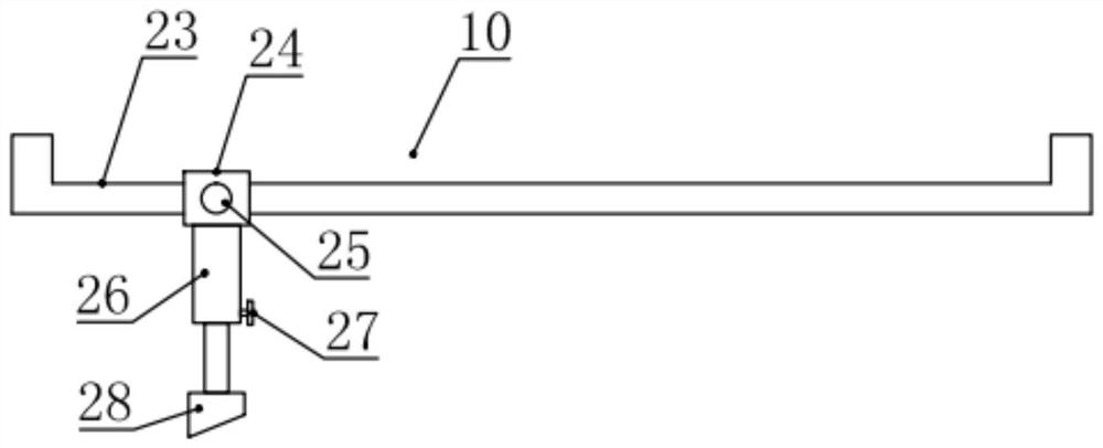
[0023] see figure 1 , in an embodiment of the present invention, a sewing machine for garment production and processing includes a pedal-operated sewing machine drive mechanism 2, supporting legs 4, a processing table 6 and a sewing machine body 8, and the sewing machine body 8 is installed on the processing table 6 for processing The corresponding sewing machine body 8 on the table 6 is provided with a processing plate 9, and a plurality of support legs 4 are installed on the underside of the processing table 6, and a sewing machine drive shaft 12 for driving the sewing machine body 8 is also installed between the plurality of support legs 4 to rotate. Pedal-operated sewing machine drive mechanism 2, the specific connection structure of the pedal-operated sewing machine drive mechanism 2 can adopt existing traditional sewing machine technology, and is not specifically limited; the drive motor 1 is also installed on the support leg 4, and the drive motor 1 The output shaft of ...
Embodiment 2
[0026] see Figure 1-4 , the difference between this embodiment and embodiment 1 is:
[0027] In this embodiment, the horizontal part of the first U-shaped frame 15 is arranged parallel to the processing table 6, the manual telescopic cylinder 22 is arranged parallel to the horizontal part of the first U-shaped frame 15, and the output shaft of the generator 17 and the drive motor 1 Coaxial setting; such as image 3 As shown, the connector 20 has a truss structure, and the side of the connector 19 facing the connector 20 is provided with a connection groove 29 that can be mated with the connector 20 to improve the reliability of the connection between the connector 19 and the connector 20 .
[0028] In this example, if figure 1 As shown, a controller 5 for controlling the lighting lamp 7 and the driving motor 1 is also installed on the supporting leg 4. The specific models and circuit connections of the controller 5, the driving motor 1 and the lighting lamp 7 are not specif...
PUM
 Abstract
Description
Claims
Application Information
 - R&D Engineer
- R&D Manager
- IP Professional
- Industry Leading Data Capabilities
- Powerful AI technology
- Patent DNA Extraction
Browse by: Latest US Patents, China's latest patents, Technical Efficacy Thesaurus, Application Domain, Technology Topic, Popular Technical Reports.
© 2024 PatSnap. All rights reserved.Legal|Privacy policy|Modern Slavery Act Transparency Statement|Sitemap|About US| Contact US: help@patsnap.com