Flapping flight device

A technology of flying device and driving device, which is applied in the field of aircraft, can solve the problems of limited application range and the need for taxiing distance on the take-off runway, and achieve the effect of reasonable structure

Inactive Publication Date: 2021-02-05
GUANGDONG GUOSHIJIAN TECH DEV CO LTD
View PDF0 Cites 0 Cited by
  • Summary
  • Abstract
  • Description
  • Claims
  • Application Information

AI Technical Summary

Problems solved by technology

Its advantage is that it has lower requirements on the take-off runway but still needs to glide distance, and it cannot hover in the air. The application range is limited

Method used


Image

  • Flapping flight device
  • Flapping flight device
  • Flapping flight device

Examples


Embodiment Construction

[0020] The technical solutions of the present invention will be described below in conjunction with the accompanying drawings and embodiments.

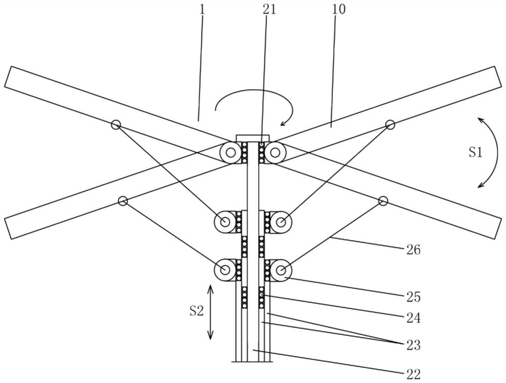
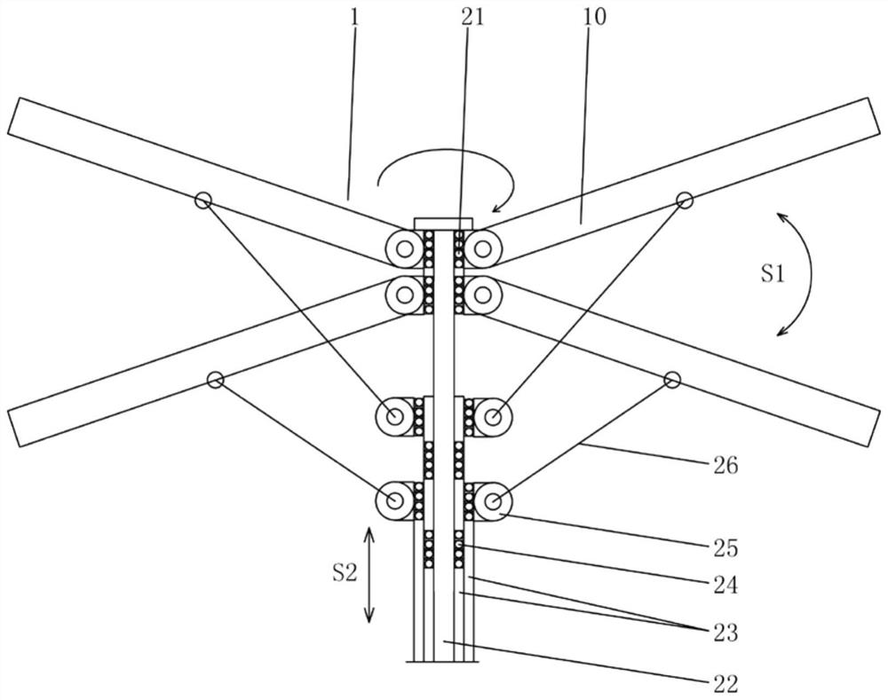
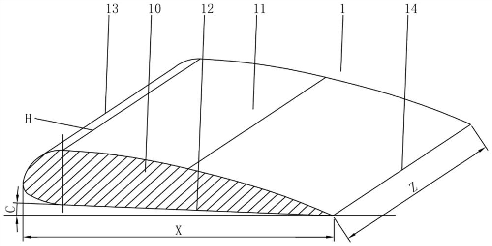
[0021] like Figure 1-3 As shown, a flapping flying device according to the present invention includes a flapping wing 1 and a driving device 2, and the flapping wing 1 includes two wings 10 and a rotating bearing 21, and the two wings 10 are arranged opposite to each other. On both sides of the rotating bearing 21, and the wings of the two wings 10 are respectively hinged on the rotating bearing 21; Each wing 10 is transmission connected. The upper plane of the wing 10 is a spoiler airfoil 11, and the lower plane of the wing 10 is a fanning airfoil 12; the spoiler airfoil 11 is composed of a front curved surface and a rear smooth surface, and the spoiler The front curved surface of the airfoil 11 protrudes upward relative to the rotation plane of the flapping wing 1 , and the spoiler airfoil 11 and the fanning airfoil 12 have an as...


PUM


Abstract

The invention relates to the technical field of aircrafts, in particular to a flapping flight device. The flapping wing comprises a flapping wing body and a driving device, the flapping wing body comprises two wing wings and a rotating bearing, the two wing wings are oppositely arranged on the two sides of the rotating bearing, and the wing roots of the two wing wings are hinged to the rotating bearing; the driving device is connected with the rotating bearing so as to be rotationally connected with the flapping wing, and the driving device is in transmission connection with the two wings respectively; the flapping wing mechanism is reasonable in structure, the driving device drives the flapping wing through vertical reciprocating motion, when the flapping wing ascends, the turbulent flowwing surface interacts with air above the turbulent flow wing surface, the air generates pressure difference between the front side curved surface and the rear smooth surface of the turbulent flow wing surface, and the direction of the pressure difference is fixed, so that the flapping wing is promoted to rotate unidirectionally; when the flapping wing descends, the flapping wing surface interactswith air below the flapping wing surface, the flapping wing rotates to enable the flapping wing surface to descend to generate a vector attack angle, and the vector attack angle enables the flappingwing surface and the air to generate vertically upward acting force.

Description

technical field [0001] The invention relates to the technical field of aircraft, in particular to a flapping flying device. Background technique [0002] The lift device of an aircraft is a mechanism based on aerodynamics. According to the structure, it can be divided into a fixed wing and a rotor. A fixed wing aircraft generally has a fuselage and a symmetrically arranged fixed wing, which is powered by a propeller to obtain a greater flight speed. and mobility. The principle of flight is that there is a relative speed between the fixed wing and the air, and the air interacts with the sides of the fixed wing to generate lift so that the aircraft obtains flight capability. The disadvantage of fixed-wing aircraft is that it cannot hover in the air, and needs to taxi on the runway to take off or land and support the construction of airport facilities. [0003] A rotorcraft such as a helicopter is characterized in that it does not need a runway when it takes off and can hover...

Claims


Application Information

Patent Timeline
Patent Type & Authority Applications(China)
IPC IPC(8): B64C33/02
CPCB64C33/02
Inventor 王志成
Owner GUANGDONG GUOSHIJIAN TECH DEV CO LTD
Why Eureka
Try Eureka