
Release film automatic processing equipment and method

A technology for processing equipment and release film, applied in thin material processing, sending objects, conveyor objects, etc., can solve problems such as increased labor costs, enterprise turnover, and impact on enterprise production and operation, and achieve the effect of improving work efficiency.

Pending Publication Date: 2021-02-02
苏州拓淼工业科技有限公司
View PDF0 Cites 2 Cited by
  • Summary
  • Abstract
  • Description
  • Claims
  • Application Information

AI Technical Summary

Problems solved by technology

However, in the film tearing process on the keyboard, manual loading and unloading is still relied on. In the labor environment where labor costs continue to rise, if loading and unloading still relies on manual labor, it will lead to an increase in the labor cost of the enterprise, and the high-intensity labor will cause the enterprise There is a large-scale resignation wave, which seriously affects the normal production and operation of the enterprise
In addition, the torn release film is scattered and piled up in the current production process, resulting in an extremely untidy production environment

Method used


Image

  • Release film automatic processing equipment and method
  • Release film automatic processing equipment and method
  • Release film automatic processing equipment and method

Examples


Embodiment Construction

[0041] Objects, advantages and features of the present invention will be illustrated and explained by the following non-limiting description of preferred embodiments. These embodiments are only typical examples of applying the technical solutions of the present invention, and all technical solutions formed by adopting equivalent replacements or equivalent transformations fall within the protection scope of the present invention.

[0042] In the description of the scheme, it should be noted that the terms "center", "upper", "lower", "left", "right", "front", "rear", "vertical", "horizontal", " The orientation or positional relationship indicated by "inner", "outer", etc. is based on the orientation or positional relationship shown in the drawings, and is only for the convenience of description and simplification of description, rather than indicating or implying that the device or element referred to must have a specific orientation , constructed and operated in a particular or...


PUM


Abstract

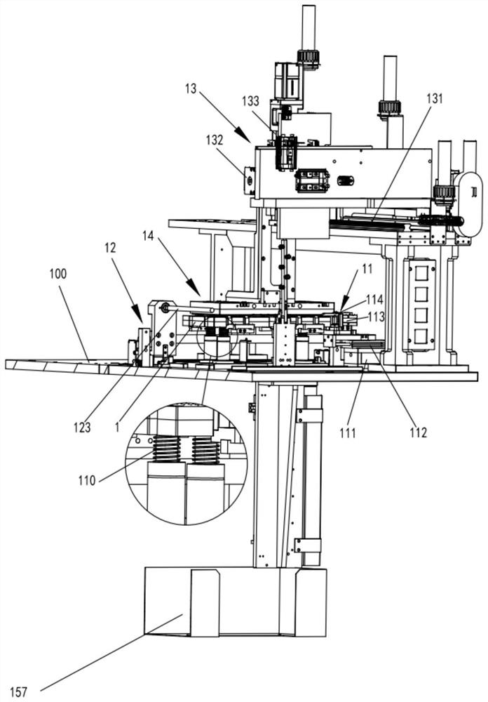
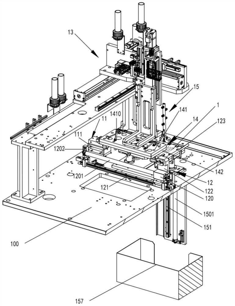
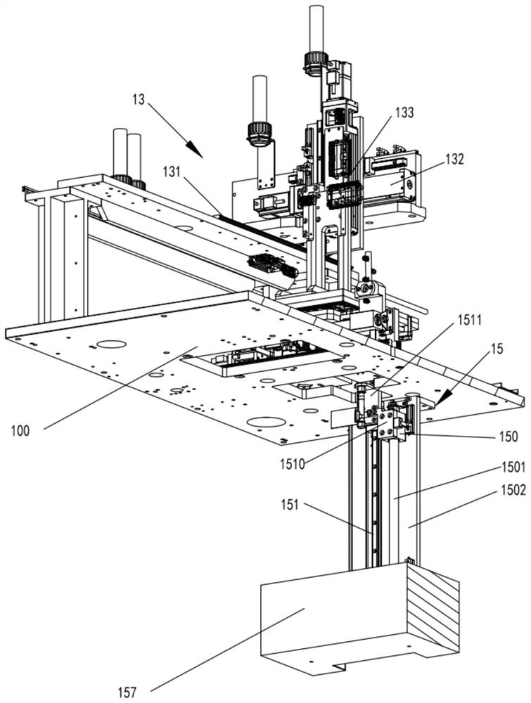
The invention discloses release film automatic processing equipment and method. The equipment comprises a bearing plate, a workbench is located above the bearing plate, the workbench and the bearing plate are elastically connected, and a product with a release film to be stripped is placed on the workbench; a transferring and pressing device is located above the workbench and applies acting forceto the workbench to adsorb and transfer the product; a clamping device is located at one end of the workbench, and the clamping face of the clamping device and the upper surface of the workbench in the stressed state are coplanar; a rolling rod is located above a clamping mechanism and separates the release film from the product, and the axis of the rolling rod is coplanar with the upper surface of the workbench in an unstressed state; a moving device drives the rolling rod to move; and a falling device is located at the other side of the workbench and enables the release film to fall into a storage box. The release film automatic processing equipment has the advantages that the workbench descends through cooperation of the transferring and pressing device and a spring, the release film isclamped through the clamping mechanism, an opening allowing the rolling rod to pass through conveniently is formed between the product and the release film after the workbench is reset, a moving mechanism drives the rolling rod to automatically strip the release film, and the working efficiency is improved.

Description

technical field [0001] The invention belongs to the technical field of mechanical manufacturing, and in particular relates to a release film automatic processing equipment and method. Background technique [0002] Along with the development of computer industry technology, the market demand for keyboards is increasing, and the demand for the said product of the present invention—keyboard film is also increasing thereupon, which requires the production of keyboard film to reach high efficiency and high efficiency. stability. The keyboard film needs to be covered with a release film during the production and transportation process. Before covering the keyboard film on the keyboard, the keyboard film needs to be separated from the release film. If the manual tearing method is used, the inefficient film tearing process will cause the entire assembly process to be damaged. Production efficiency is reduced. At present, the rotating airflow tearing method can not only replace the...

Claims


Application Information

Patent Timeline
IPC IPC(8): B65G47/91B65H41/00B65H29/24
CPCB65G47/91B65H29/241B65H41/00
Inventor 金浩
Owner 苏州拓淼工业科技有限公司
Learn More