
Phase-change switch optimal configuration method and system based on particle swarm optimization algorithm

A particle swarm optimization, commutation switch technology, applied in the direction of calculation, calculation model, circuit device, etc., can solve the problem of ignoring the current phase angle, the installation point configuration of the commutation switch has not been studied, and the current unbalance cannot be accurately represented, etc. problem, to achieve the effect of reasonable configuration

Active Publication Date: 2021-01-29
STATE GRID SHANDONG ELECTRIC POWER COMPANY RIZHAOPOWER SUPPLY +2
View PDF4 Cites 2 Cited by
  • Summary
  • Abstract
  • Description
  • Claims
  • Application Information

AI Technical Summary

Problems solved by technology

When installing a reversing switch, loads that are sensitive to power quality requirements should be avoided; installers usually install according to their own experience and the imbalance of each branch circuit, but the inventor believes that this method is inevitable. The difference in the treatment effect of the three-phase unbalance is caused. Although certain configuration principles are proposed for the installation and configuration of the phase-change switch, no research has been done on the configuration of the installation point of the phase-change switch. In actual projects, the installation staff mainly Determine the location point based on your own experience, and then install the reversing switch
[0005] In addition, by calculating the phase unbalance degree based on the effective value of the user load current, active power, and electricity consumption of the distribution network as reference information, there is a problem of ignoring the asymmetry of the current phase angle; only the current effective value, or reactive power , the degree of current unbalance cannot be accurately represented only by considering the active power; and the problem of load characteristics cannot be truly reflected only by the effective value of current and voltage, so in the configuration of the commutation switch, the three-phase unbalance and load characteristic

Method used


Image

  • Phase-change switch optimal configuration method and system based on particle swarm optimization algorithm
  • Phase-change switch optimal configuration method and system based on particle swarm optimization algorithm
  • Phase-change switch optimal configuration method and system based on particle swarm optimization algorithm

Examples


Embodiment 1

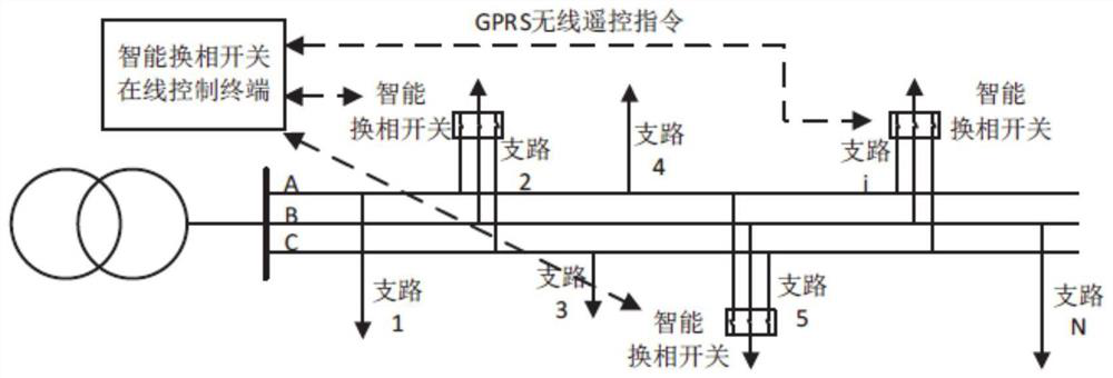
[0040] The commutation switch used in this embodiment is mainly composed of two parts: the control terminal of the commutation switch and the execution terminal of the commutation switch, wherein the control terminal of the commutation switch is used as the output terminal of the commutation command, and the control terminal and the execution terminal pass through Data transmission realizes information interaction, realizes phase sequence switching of single-phase load according to information interaction, and finally realizes three-phase unbalance control of distribution station area.

[0041] Such as figure 1 As shown, the commutation switch control terminal is configured in the distribution station area, and the load commutation execution terminal is added. The comprehensive control terminal detects the load user data of the low-voltage side of the distribution transformer and each phase commutation switch installation point in real time, and through the three-phase unbalanc...

Embodiment 2

[0156] This embodiment provides a commutation switch optimization configuration system based on particle swarm optimization algorithm, including:

[0157] The model building module is used to construct a commutation switch configuration model according to user load power and distribution network topology node impedance;

[0158] The solution module is used to minimize the three-phase unbalance degree and the number of commutation switch actions as the objective function, and use the particle swarm optimization algorithm to solve the configuration model of the commutation switch to obtain the optimal switching action of the commutation switch;

[0159] The execution module is used to determine the load participating in the commutation according to the change of the load before and after the optimal switching action of the commutation switch;

[0160] The selection module is used to sort the commutation times of the loads participating in the commutation, and the position of the...


PUM


Abstract

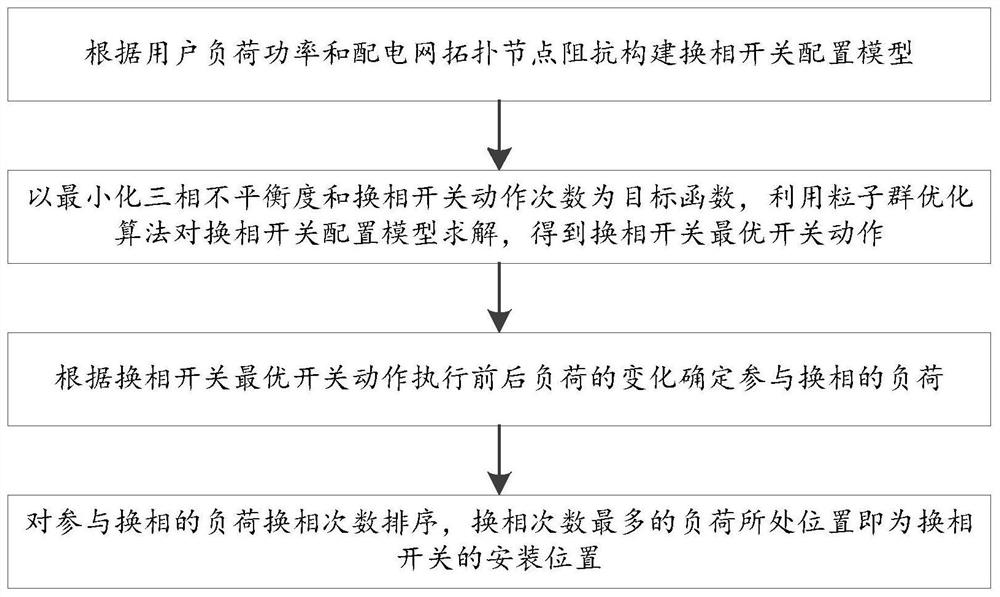
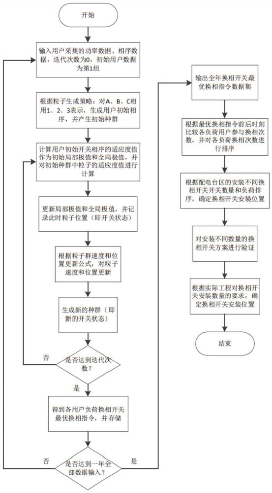
The invention discloses a phase-change switch optimal configuration method and system based on a particle swarm optimization algorithm. The method comprises the steps of: constructing a phase-change switch configuration model according to user load power and power distribution network topology node impedance; solving the phase-change switch configuration model by using a particle swarm optimization algorithm by taking the minimized three-phase unbalance degree and the action times of the phase-change switch as target functions to obtain the optimal switch action of the phase-change switch; determining the load participating in commutation according to the change of the load before and after the optimal switching action of the commutation switch is executed; sorting the commutation times ofthe loads participating in commutation, wherein the position of the load with the maximum commutation times is the installation position of the commutation switch; and establishing a phase-change switch configuration model according to the topological structure of the power distribution network and the load power data, solving the model by using a particle swarm optimization algorithm by taking the three-phase unbalance degree and the phase-change frequency as targets, and determining the installation position of the phase-change switch according to the optimal solution, thereby realizing reasonable configuration of the phase-change switch.

Description

technical field [0001] The invention relates to the technical field of power quality control, in particular to a commutation switch optimization configuration method and system based on a particle swarm optimization algorithm. Background technique [0002] The statements in this section merely provide background information related to the present invention and do not necessarily constitute prior art. [0003] There are many types of supply loads in the actual distribution station area, and the density of each load is different. The fluctuation of the load itself will increase the degree of unbalance of the three phases; the phase sequence switching of the load through the intelligent phase change switch can realize the balanced configuration of the load , realize the treatment of three-phase unbalance, and can avoid the problems of slow and high risk of manual commutation operation. [0004] The phase change switch only contains one control terminal and several execution te...

Claims


Application Information

Patent Timeline
IPC IPC(8): H02J3/00H02J3/26G06N3/00G06Q10/04G06Q50/06
CPCH02J3/00H02J3/26G06N3/006G06Q10/04G06Q50/06H02J2203/20Y02E40/50
Inventor 张宗峰符奥张国飞王海江张锐曹立霞李成栋辛征阎俏郑学汉刘辉利
Owner STATE GRID SHANDONG ELECTRIC POWER COMPANY RIZHAOPOWER SUPPLY
Learn More