Automatic discharging and positioning mechanism for scaffold cross rod

A technology of positioning mechanism and automatic discharge, which is applied in the direction of conveyor objects, metal material coating process, coating, etc., can solve the problems of high labor intensity of employees, reduce the efficiency of pendants, increase labor costs, etc., and achieve work efficiency. The effect of wide coverage and shortened takt time

Pending Publication Date: 2021-01-29
徐州瑞马智能技术有限公司
View PDF0 Cites 3 Cited by
  • Summary
  • Abstract
  • Description
  • Claims
  • Application Information

AI Technical Summary

Problems solved by technology

[0003] At present, in the galvanizing production line of scaffold cross-bars, the cross-bars are basically in a disordered state in the transfer frame, and the cross-bars are in the form of manual hanging during the material-hanging process. Since the cross-bars need to be hot-dip galvanized in a specific position In order to ensure the best galvanizing effect, the use of workers to scrape materials greatly increases the labor cost, reduces the efficiency of the pendant, and the labor intensity of the staff is also high, which is prone to more mistakes and also has a lot of safety risks.

Method used


Image

  • Automatic discharging and positioning mechanism for scaffold cross rod

Examples


Embodiment Construction

[0018] The present invention will be further described below in conjunction with the accompanying drawings and specific embodiments, so that those skilled in the art can better understand the present invention and implement it, but the examples given are not intended to limit the present invention.

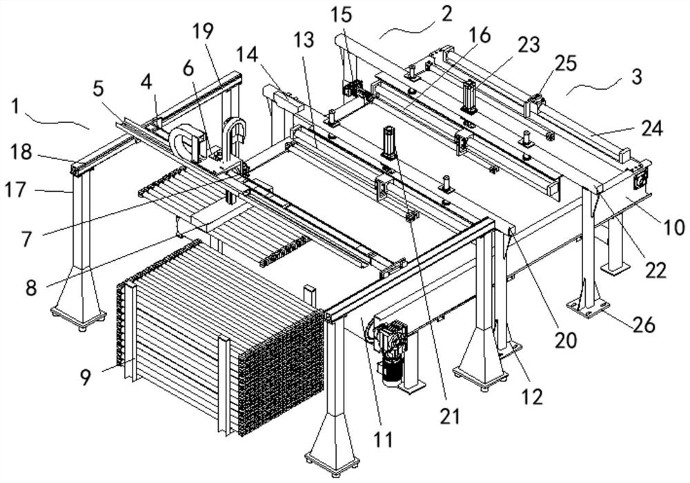
[0019] refer to figure 1 As shown, an embodiment of a scaffold crossbar 18 automatic discharge positioning mechanism 2 of the present invention includes a feeding mechanism 1, a positioning mechanism 2 and a blanking mechanism 3, and the feeding mechanism 1 includes a symmetrically arranged transfer device, two A moving rod 4 is arranged in the transfer device, a first rail 5 is arranged on the moving rod 4, a moving block 6 is arranged on the first rail 5, a motor 7 is arranged on the moving block 6, and a suction plate 8 is arranged on the motor 7 , a material frame 9 is arranged below the suction plate 8; the positioning mechanism 2 and the blanking mechanism 3 are both arrange...


PUM


Abstract

The invention discloses an automatic discharging and positioning mechanism for a scaffold cross rod. The automatic discharging and positioning mechanism is characterized by comprising a feeding mechanism, a positioning mechanism and a discharging mechanism, wherein the feeding mechanism comprises transfer devices which are symmetrically arranged, a moving rod is arranged in the two transfer devices, a first rail is arranged on the moving rod, a moving block is arranged on the first rail, a motor is arranged on the moving block, a material suction plate is arranged on the motor, and a materialframe is arranged below the material suction plate; and the positioning mechanism and the discharging mechanism are arranged on a workbench, a conveying belt is arranged on the workbench, the positioning mechanism comprises a first material door and a second material door, the first material door comprises a first limiting rod and a visual identification mechanism, and the second material door comprises a rotating air cylinder and a second limiting rod. The automatic discharging and positioning mechanism is simple in structure, and automatic discharging and positioning of the scaffold cross rod can be realized, so that the automatic hanging requirement of a robot is met, the labor intensity of workers is reduced, the efficiency is improved, and the labor cost of enterprises is reduced.

Description

technical field [0001] The invention relates to the field of galvanizing devices, in particular to an automatic discharge and positioning mechanism for scaffold crossbars. Background technique [0002] Hot-dip galvanizing, that is, hot-dip galvanizing, also called hot-dip galvanizing and hot-dip galvanizing: it is an effective metal anti-corrosion method, mainly used in metal structure facilities in various industries. It is to immerse the rust-removed steel parts in the molten zinc at about 500 ℃, so that the surface of the steel parts will be attached with a zinc layer, so as to achieve the purpose of anti-corrosion. Hot-dip galvanizing process: pickling of finished product - water washing - adding auxiliary plating solution - drying - rack plating - cooling - passivation - cleaning - grinding - hot galvanizing completed. [0003] At present, in the galvanizing production line of scaffold cross-bars, the cross-bars are basically in a disordered state in the transfer mater...

Claims


Application Information

Patent Timeline
Patent Type & Authority Applications(China)
IPC IPC(8): B65G47/74B65G47/22C23C2/06
CPCB65G47/22B65G47/74C23C2/06
Inventor 戴海峰凌波蒋庆飞宗欢欢
Owner 徐州瑞马智能技术有限公司
Why Eureka
Try Eureka