A tire installation equipment for chemical production
A technology for installation equipment and chemical production, applied in tire installation, tire parts, transportation and packaging, etc., can solve the problems of manual loading and unloading, low installation efficiency, high labor intensity, etc., to reduce manual unloading. effect of operation
- Summary
- Abstract
- Description
- Claims
- Application Information
AI Technical Summary
Problems solved by technology
Method used
Image

Examples
Embodiment 1
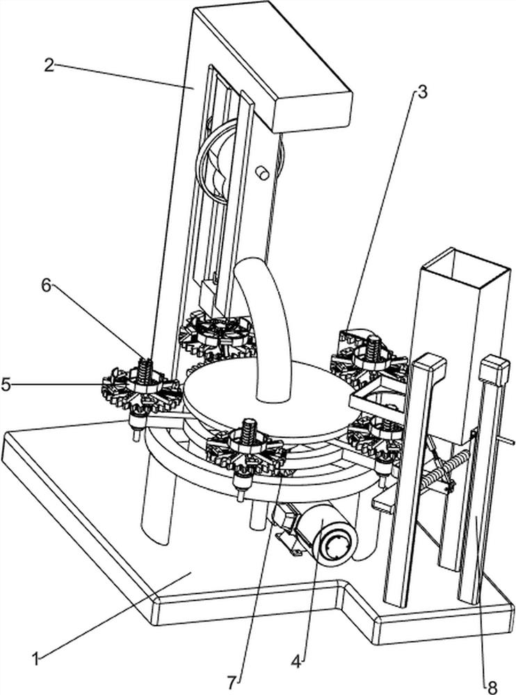
[0030] A kind of tire installation equipment for chemical production, such as figure 1 and figure 2 As shown, it includes a bottom plate 1, a profile 2, a column rack 3, a press-down mechanism 4, an expansion mechanism 5 and a push-up mechanism 6. There is a column rack 3, a pressing mechanism 4 is arranged between the bottom plate 1 and the profile 2, an expansion mechanism 5 is provided on the bottom plate 1, the expansion mechanism 5 is engaged with the column rack 3, and the expansion mechanism 5 is engaged with the profile frame 2, expanding A push-up mechanism 6 is provided on the mechanism 5 .
[0031] When chemical industry workers need to install wheel hubs on tires, the workers can use this installation equipment, first manually place multiple tires on the extension mechanism 5 one by one, put the wheel hubs on the push-up mechanism 6 one by one, and then start the downward pressure Mechanism 4, the pressing mechanism 4 reciprocates up and down in a straight line,...
Embodiment 2
[0033] On the basis of Example 1, as image 3 , Figure 4 , Figure 5 , Image 6 and Figure 7 As shown, the pressing mechanism 4 includes a motor 41, a first transmission shaft 42, a second transmission shaft 43, a pulley assembly 44, a cam 45, a first push rod 46, a pressure wheel block 47 and a first fixed frame 48. The bottom plate 1 A motor 41 is installed on the upper front side, the output shaft of the motor 41 is connected with a first transmission shaft 42, the first transmission shaft 42 is rotatably connected with the bottom plate 1, and the upper part of the frame 2 is rotatably provided with a second transmission shaft 43, the second transmission shaft A pulley assembly 44 is connected between the rear part of 43 and the rear part of the first transmission shaft 42, a cam 45 is arranged in the middle of the second transmission shaft 43, a first push rod 46 is slidably provided on the outer side of the cam 45, and the bottom of the first push rod 46 is provided ...
Embodiment 3
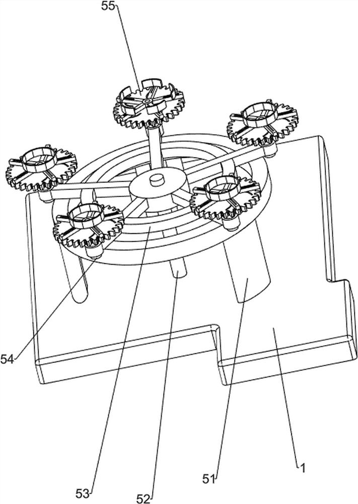
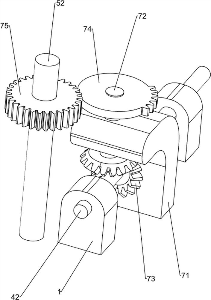
[0040] On the basis of Example 2, as Figure 8 , Figure 9 and Figure 10 As shown, it also includes a rotating mechanism 7, the bottom plate 1 is provided with a rotating mechanism 7, and the rotating mechanism 7 includes a support plate 71, a fourth transmission shaft 72, a bevel gear set 73, a missing gear 74 and a full gear 75, on the bottom plate 1 A support plate 71 is arranged in the middle, a fourth transmission shaft 72 is rotatably arranged on the upper part of the support plate 71 , a bevel gear set 73 is arranged between the lower part of the fourth transmission shaft 72 and the first transmission shaft 42 , and the upper part of the fourth transmission shaft 72 is provided with a bevel gear set 73 . The gear 74 is missing, the upper part of the third transmission shaft 52 is provided with a full gear 75 , and the full gear 75 meshes with the missing gear 74 .
[0041] The rotation of the first drive shaft 42 drives the bevel gear set 73 to rotate, thereby drives...
PUM
 Abstract
Description
Claims
Application Information
 - R&D
- Intellectual Property
- Life Sciences
- Materials
- Tech Scout
- Unparalleled Data Quality
- Higher Quality Content
- 60% Fewer Hallucinations
Browse by: Latest US Patents, China's latest patents, Technical Efficacy Thesaurus, Application Domain, Technology Topic, Popular Technical Reports.
© 2025 PatSnap. All rights reserved.Legal|Privacy policy|Modern Slavery Act Transparency Statement|Sitemap|About US| Contact US: help@patsnap.com