A high-power motor slip ring replacement device

A high-power, slip ring technology, applied in the direction of electromechanical devices, manufacturing motor generators, electrical components, etc., can solve the problems of motor slip ring replacement, inconvenient disassembly, etc., to improve applicability, improve fixation and guiding effects Effect

Active Publication Date: 2022-02-25
深圳能茨科技有限公司
View PDF12 Cites 0 Cited by
  • Summary
  • Abstract
  • Description
  • Claims
  • Application Information

AI Technical Summary

Problems solved by technology

[0003] After retrieval, the Chinese patent application number is CN209844776U, which discloses a micro-motor replacement slip ring device, including a fixing seat, two hydraulic rods are fixed on both sides of the outer wall of the top of the fixing seat, and the two adjacent The top outer wall of the hydraulic rod is fixed with a fixed block, and the cross section of the two fixed blocks is L-shaped, but the above technical solution can only replace the slip ring of the motor removed from the equipment, so there is still no The problem of being able to replace slip rings on motors installed on equipment that are inconvenient to disassemble and that are at various angles

Method used


Image

  • A high-power motor slip ring replacement device
  • A high-power motor slip ring replacement device
  • A high-power motor slip ring replacement device

Examples


Embodiment Construction

[0029] The technical solution of this patent will be further described in detail below in conjunction with specific embodiments.

[0030] Embodiments of the present patent are described in detail below, examples of which are shown in the drawings, wherein the same or similar reference numerals designate the same or similar elements or elements having the same or similar functions throughout. The embodiments described below by referring to the figures are exemplary and are only used for explaining the patent, and should not be construed as limiting the patent.

[0031] In the description of this patent, it is to be understood that the terms "center", "upper", "lower", "front", "rear", "left", "right", "vertical", "horizontal", The orientation or positional relationship indicated by "top", "bottom", "inner", "outer", etc. is based on the orientation or positional relationship shown in the drawings, and is only for the convenience of describing this patent and simplifying the des...


PUM


Abstract

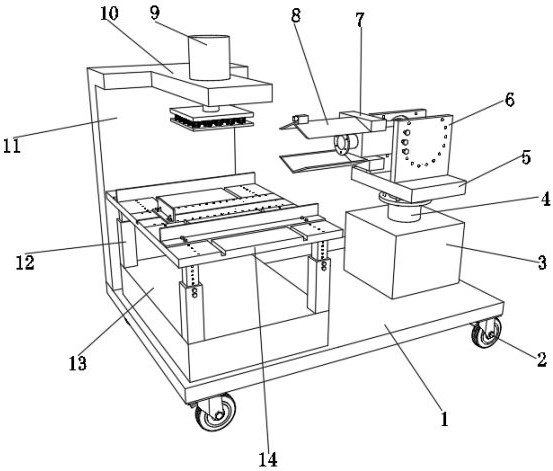
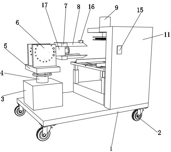
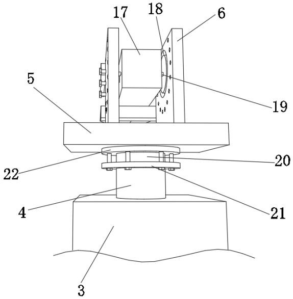
The invention discloses a high-power motor slip ring replacement device, which relates to the technical field of motor slip ring installation; in order to solve the problem that the slip ring cannot be replaced for a motor installed on equipment that is inconvenient to disassemble and is at various angles; the present invention The device specifically includes a bottom plate, four universal wheels are respectively provided at the four corners of the bottom outer wall of the bottom plate, a support platform and an electro-hydraulic lifting rod are arranged on the top outer wall of the bottom plate, and four telescopic rods are respectively provided at the four corners of the outer wall of the support platform top, The top outer walls of the four telescopic rods are provided with motor placement plates. In the present invention, by setting the fixed plate, the rotating shaft and the rotating plate, the staff first removes the screws used to fix the rotating plate and the fixed plate, and then the mounting plate can be rotated to the opposite direction through the rotating shaft, so that the second The output shaft of the electric push rod points to the other side of the motor placement plate, so as to prevent the motor placement plate from affecting the replacement of the slip ring.

Description

technical field [0001] The invention relates to the technical field of motor slip ring installation, in particular to a high-power motor slip ring replacement device. Background technique [0002] Motor slip rings are also called conductive rings, collector rings, bus rings, etc. It can be used in any electromechanical system that requires continuous rotation while transmitting power and signals from a fixed position to a rotating position. Motor slip ring series Synchronous motors and asynchronous motors, which use collector rings, are widely used in industrial sectors, and most of them operate under various harsh conditions. Although these motors do not have the same reversing effect as DC motors, like commutators, they also suffer from abnormal wear of motor slip rings or brushes, vibration of brushes, and generation of sparks. Especially from the perspective of brush material, not only graphite brushes are used for motor slip ring brushes, but also metal graphite brush...

Claims


Application Information

Patent Timeline
Patent Type & Authority Patents(China)
IPC IPC(8): H02K15/00
CPCH02K15/0006
Inventor 龚爽
Owner 深圳能茨科技有限公司
Why Eureka
Try Eureka