
Drilling mechanism for pcb circuit board

A technology of PCB circuit board and drilling mechanism, used in metal processing and other directions, can solve the problems of large size, poor functionality, and inability to reasonably clean dust, and achieve the effect of improving functionality, easy welding, and high flexibility

Inactive Publication Date: 2021-05-04
江苏洲旭电路科技有限公司
View PDF13 Cites 0 Cited by
  • Summary
  • Abstract
  • Description
  • Claims
  • Application Information

AI Technical Summary

Problems solved by technology

[0003] In the drilling process, it is necessary to use clamping equipment to fix the circuit board. These clamping devices are large in size and cannot be adapted to small workbenches, and the cost of large clamping equipment is high, and they are flexible, inventive, and functional. Poor, for example, during the drilling process, the drilled dust cannot be properly cleaned, etc.

Method used


Image

  • Drilling mechanism for pcb circuit board
  • Drilling mechanism for pcb circuit board
  • Drilling mechanism for pcb circuit board

Examples


Embodiment Construction

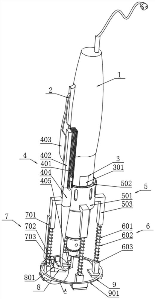
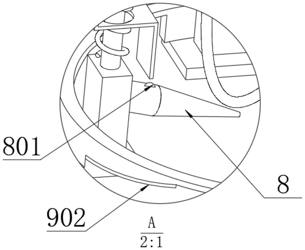
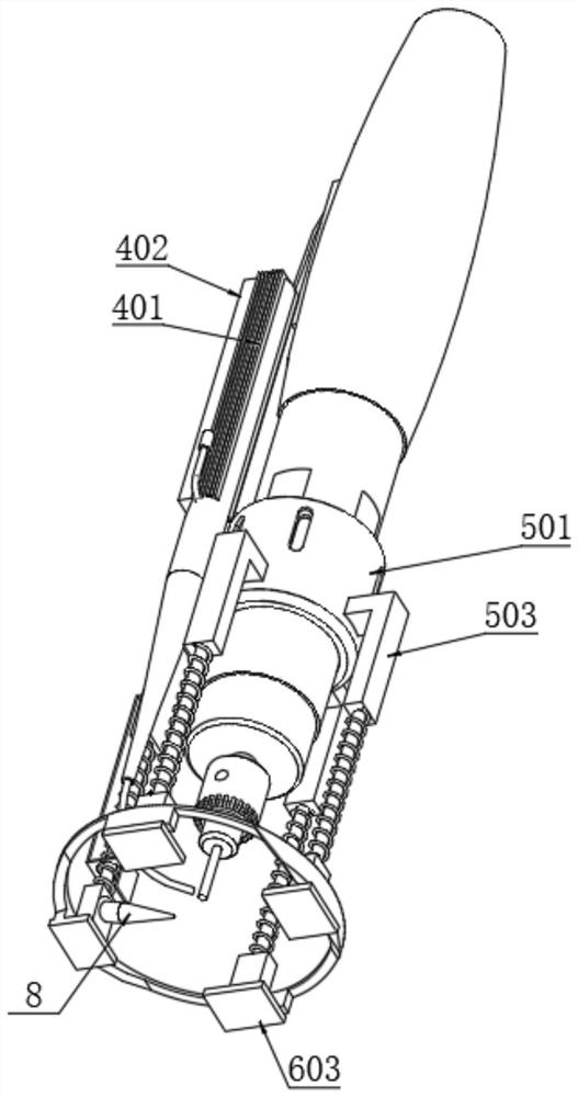
[0031] Refer to attached Figure 1-8 , a drilling mechanism for a PCB circuit board, comprising a drill pipe main shaft 1, a liquid cavity mechanism 4, a snap ring mechanism 5, a pressure rod mechanism 6, a starting mechanism 7, a fan cylinder 8 and a metal ring 9, the middle part of the drill pipe main shaft 1 There are four notches 3, and a limiting plate 301 is arranged in the notch 3, and a limiting ball 30101 is arranged on the outer wall of the limiting plate 301. ,like Figure 5 , Figure 8 As shown, the limiting plate 301 is installed in the notch 3 by means of a rotating shaft connection, and a spring plate 302 is connected between the bottom surface of the limiting plate 301 and the inner surface of the notch 3, and is fastened to the drill in a spring-pressed connection. The snap ring 501 on the rod main shaft 1 is limited and fixed. When removing the snap ring 501, you only need to press the limit plate 301 to remove the snap ring 501. It can be seen from this th...


PUM


Abstract

The invention relates to a drilling mechanism for a PCB circuit board, comprising a drill rod main shaft, a liquid chamber mechanism, a snap ring mechanism, a pressing rod mechanism, a starting mechanism, a fan cylinder and a metal ring, and four slots are opened in the middle of the drill pipe main shaft There is a limit plate in the notch, and a limit ball is set on the outer wall of the limit plate. The snap ring mechanism is set in the middle of the drill pipe main shaft, and the ring cavity inside the snap ring is opened and the inner wall of the snap ring is used for snapping. The limit hole on the limit ball, the outer wall of the snap ring is welded with four arm rods, and the four arm rods are also inserted with a pressure rod mechanism; in this way, the glue is applied to the drilled hole, so that It is convenient for components to be pre-fixed after insertion, which is convenient for welding, and the functionality is improved again, and the top of the liquid chamber mechanism is provided with a socket-type connecting plate, which can be removed from the drill pipe spindle switch as required. The application is more flexible when the liquid chamber mechanism does not need to inject glue.

Description

technical field [0001] The invention relates to the technical field of drilling devices, in particular to a drilling mechanism for a PCB circuit board. Background technique [0002] Printed circuit boards {Printed circuit boards}, also known as printed circuit boards, are providers of electrical connections for electronic components, collectively referred to as PCB circuit boards, circuit boards are used in the electronics industry, and are used to fix various components in integrated circuits. The circuit board makes the circuit miniaturized and intuitive, and plays an important role in the mass production of fixed circuits and the optimization of the layout of electrical appliances. In the process of component replacement or maintenance, the drill spindle is often used to punch holes on the circuit board, and then the components Install. [0003] In the drilling process, it is necessary to use clamping equipment to fix the circuit board. These clamping devices are large i...

Claims


Application Information

Patent Timeline
Patent Type & Authority Patents(China)
IPC IPC(8): B26F1/16B26D7/18B26D7/01B26D7/27
CPCB26D7/01B26D7/1854B26D7/27B26F1/16B26F2210/08
Inventor 闻国平
Owner 江苏洲旭电路科技有限公司
Learn More