Garden pruning equipment
A kind of pruning equipment and gardening technology, applied in the field of pruning equipment, can solve the problems of inability to collect branches and leaves, inconvenient pruning of circular landscape trees, etc., and achieve the effect of easy pruning work
- Summary
- Abstract
- Description
- Claims
- Application Information
AI Technical Summary
Problems solved by technology
Method used
Image
Examples
Embodiment 1
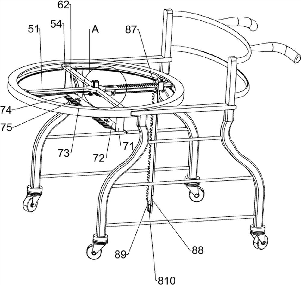
[0029] A garden pruning equipment such as figure 1 , figure 2 , image 3 and Image 6 As shown, it includes a support frame 1, casters 2, push handle 3, circular slide rail 4, sliding mechanism 5, transmission mechanism 6, cross-cutting mechanism 7, vertical cutting mechanism 8, and the front and rear sides of the bottom of the push handle 3 are connected There is a support frame 1, the left and right sides of the bottom of the support frame 1 are connected with casters 2, the upper parts of the two support frames 1 are connected with a circular slide rail 4, and the circular slide rail 4 is provided with a sliding mechanism 5, the sliding mechanism 5 is respectively provided with a transmission mechanism 6, a cross-cutting mechanism 7 and a vertical cutting mechanism 8, and the transmission mechanism 6 is connected with the cross-cutting mechanism 7 and the vertical cutting mechanism 8 respectively.
[0030] The sliding mechanism 5 includes a cross slide bar 51, an equidi...
Embodiment 2
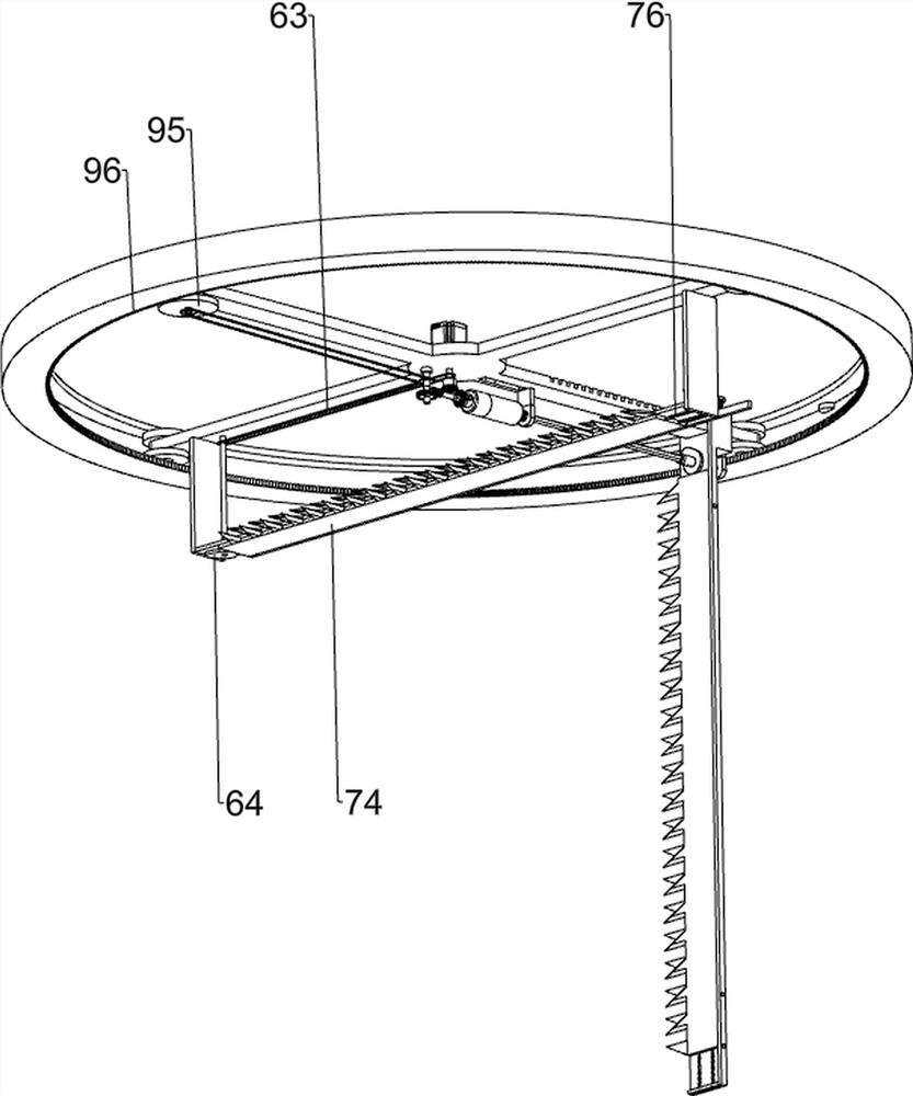
[0036] On the basis of Example 1, such as figure 1 , image 3 and Image 6 Shown, also comprise rotating mechanism 9, and rotating mechanism 9 comprises first worm screw 91, rotating rod 92, first worm gear 93, second belt transmission group 94, sector gear 95 and ring gear 96, the hexagonal rotating shaft 82 The left end is connected with a first worm 91, and the middle of the bottom of the cross slide bar 51 is rotatably connected with a rotating rod 92. The side rotation type is connected with a sector gear 95, a second belt transmission group 94 is connected between the transmission shaft of the sector gear 95 and the rotating rod 92, and a ring gear 96 is connected to the inner wall of the circular slide rail 4, and the ring gear 96 meshes with the sector gear 95 .
[0037] The rotation of the hexagonal shaft 82 drives the first worm 91 to rotate, the first worm 91 rotates through the first worm gear 93 to drive the rotation rod 92 to rotate, the rotation rod 92 rotate...
Embodiment 3
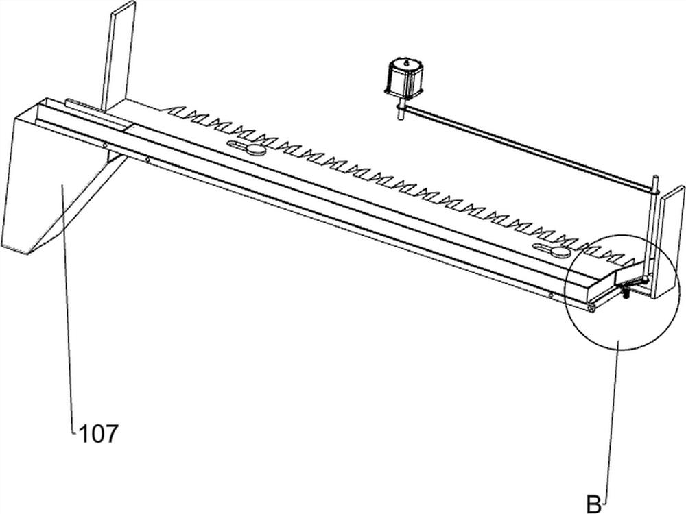
[0039] On the basis of Example 2, such as figure 1 , Figure 4 and Figure 7 As shown, a waste material conveying mechanism 10 is also included, and the waste material conveying mechanism 10 includes a mounting plate 101, a third belt drive group 102, a second worm screw 103, a second turbine 104, a conveyor belt group 105, a baffle plate 106 and a funnel hopper 107, The rear side of the top of the first cutter 72 is connected with a mounting plate 101, the mounting plate 101 is connected with a second worm 103 in a rotational manner, the third belt transmission group 102 is connected between the second worm 103 and the rotating rod 62, and the top of the first cutter 72 The rear side is connected with a baffle plate 106, and the baffle plate 106 is positioned at the front side of the mounting plate 101, and a conveyor belt set 105 is rotatably connected between the baffle plate 106 and the first cutter 72, and the transmission shaft of the conveyor belt set 105 is connected ...
PUM
 Abstract
Description
Claims
Application Information
 - R&D Engineer
- R&D Manager
- IP Professional
- Industry Leading Data Capabilities
- Powerful AI technology
- Patent DNA Extraction
Browse by: Latest US Patents, China's latest patents, Technical Efficacy Thesaurus, Application Domain, Technology Topic, Popular Technical Reports.
© 2024 PatSnap. All rights reserved.Legal|Privacy policy|Modern Slavery Act Transparency Statement|Sitemap|About US| Contact US: help@patsnap.com


