A blade edge computing device based on cpci architecture

A computing device and edge computing technology, applied in digital transmission systems, data exchange networks, electrical components, etc., can solve problems such as poor heat dissipation of machines, affecting real-time data transmission, crashes, etc., to meet performance requirements and improve equipment applications Performance, the effect of accelerating the cooling process

Active Publication Date: 2021-04-02
广东利通科技投资有限公司 +1
View PDF6 Cites 0 Cited by
  • Summary
  • Abstract
  • Description
  • Claims
  • Application Information

AI Technical Summary

Problems solved by technology

[0004] In the prior art, due to the unreasonable design of the slot on the backplane, the data transmission path of the switch board, the system board and the service board is not good, which affects the real-time performance of data transmission, and causes the edge computing device to be in some real-time scenarios, such as, When collecting traffic video data, it is difficult to collect the required data in real time, which affects the performance of the equipment. In addition, data transmission between the service board and the switch board should be performed when necessary. When there is no data collection, the service board is in the working state, which will lead to high power consumption
[0005] In addition, in the prior art, in the circuit design of the backplane and the switching board, due to the dense layout of the chips, the crosstalk between the chips is relatively serious. How to shield the crosstalk between the chips is also a difficult problem in high-performance computing. There is a heat dissipation problem. In the existing edge computing equipment, due to the unreasonable installation position of the cooling fan, the heat dissipation performance of the machine is poor, and the machine is fatal, which affects the user experience.

Method used


Image

  • A blade edge computing device based on cpci architecture

Examples


Embodiment Construction

[0022] The application will be further described in detail below in conjunction with the accompanying drawings and embodiments. It should be understood that the specific embodiments described here are only used to explain related inventions, rather than to limit the invention. It should also be noted that, for the convenience of description, only the parts related to the related invention are shown in the drawings.

[0023] It should be noted that, in the case of no conflict, the embodiments in the present application and the features in the embodiments can be combined with each other. The present application will be described in detail below with reference to the accompanying drawings and embodiments.

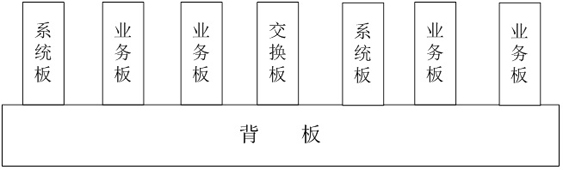
[0024] figure 1 It shows a blade type edge computing device based on CPCI architecture of the present invention, the computing device includes a backplane, a switching board, multiple service boards, a first system board and a second system board; the switching board Instal...


PUM


Abstract

The invention provides a blade type edge computing device based on CPCI architecture, the computing device includes a backplane, a switching board, multiple service boards, a first system board and a second system board; the switching board is installed in the middle of the backplane position, the first system board is installed in the first direction of the backplane in a manner close to the switch board, and some service boards among the multiple service boards are installed in the first direction of the backplane in the direction away from the same side of the first system board , the other service boards in the service boards are installed in the second direction of the switch board in a way that is far away in turn, the second system board is installed on the farthest side of the switch board in the second direction, and the switch board installed in the middle position is used to Provide optimal data transmission paths between the system board and multiple service boards and between multiple service boards. The optimal transmission path is arranged based on the heat dissipation of the system board and the priority among multiple service boards, thereby improving the data transmission performance between the service board and the system board.

Description

technical field [0001] The invention relates to the technical field of computer hardware, in particular to a blade edge computing device based on CPCI architecture. Background technique [0002] With the continuous improvement of the theoretical framework of smart high-speed, the technical characteristics of smart communication stations as "node" equipment have gradually become clear through continuous exploration, and the technical characteristics of smart high-speed edge computing equipment, the core equipment of smart communication stations, have become very clear. Existing edge computing devices have high cost and poor scalability, and edge node devices have single functions and narrow applicable fields. [0003] According to the requirements of the application, the smart high-speed edge computing device should have at least the following performance: open hardware architecture. The open architecture facilitates the convenient access of third-party components, allowing ...

Claims


Application Information

Patent Timeline
Patent Type & Authority Patents(China)
IPC IPC(8): H04L12/931H04L12/947H04Q1/02
CPCH04L49/25H04L49/40H04Q1/035H04Q1/15H04Q1/155
Inventor 戴连贵邢万勇李从凡修战宇严桂灵侯林汝符敏杰
Owner 广东利通科技投资有限公司
Why Eureka
Try Eureka