
Energy storage system and carrier synchronization method thereof

A carrier synchronization and energy storage system technology, applied in the field of power electronics, can solve problems such as inconsistency in multi-machine transmission, and achieve the effect of improving control system interference

Pending Publication Date: 2021-01-22
SHENZHEN HOPEWIND ELECTRIC CO LTD
View PDF4 Cites 0 Cited by
  • Summary
  • Abstract
  • Description
  • Claims
  • Application Information

AI Technical Summary

Problems solved by technology

[0004] In view of this, the purpose of this application is to provide an energy storage system and its carrier synchronization method to solve the problem of inconsistency in wave transmission between multiple machines in the existing energy storage system

Method used


Image

  • Energy storage system and carrier synchronization method thereof
  • Energy storage system and carrier synchronization method thereof
  • Energy storage system and carrier synchronization method thereof

Examples


Embodiment 1

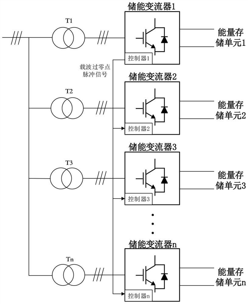
[0028] Such as image 3 As shown, the embodiment of the present application provides an energy storage system, and the energy storage system includes an energy storage converter 1 to an energy storage converter n, an energy storage unit 1 to an energy storage unit n, an isolation transformer 1 to an isolation transformer n.

[0029] In this example, the application range of each energy storage converter is 20kW-300kW. Each energy storage converter is an energy storage converter with AC / DC single-stage topology; or, each energy storage converter is an energy storage converter with AC / DC and DC / DC two-stage topology device.

[0030] In this example, each energy storage unit includes one or more battery packs.

[0031] Wherein, the DC end of each energy storage converter is connected to an energy storage unit, and the AC end of each energy storage converter is connected to an isolation transformer, for example: the DC end of the energy storage converter 1 is connected to the e...

Embodiment 2

[0039] Such as Figure 5 As shown, different from Embodiment 1, the energy storage converter further includes a centralized controller; the energy storage converter 1 is configured to send the carrier synchronization signal to the centralized controller, and the The centralized controller sends the carrier synchronization signal to energy storage converter 2 to energy storage converter n, so that all energy storage converters realize carrier synchronization.

[0040] based on Figure 5 For the energy storage system shown, the embodiment of the present application also provides a carrier synchronization method of the energy storage system, the method is used in a centralized controller, and the method includes:

[0041] S21. Obtain a carrier synchronization signal sent by any one of the energy storage converters among the plurality of energy storage converters;

[0042] S22. Send the carrier synchronization signal to other energy storage converters, so that all energy storage...


PUM


Abstract

The invention discloses an energy storage system and a carrier synchronization method thereof. The energy storage system comprises a plurality of energy storage converters, wherein the direct currentend of each energy storage converter is connected with an energy storage unit, all the alternating current ends of the energy storage converters are connected together and then connected with a powergrid, any one energy storage converter in the plurality of energy storage converters is configured to acquire a carrier synchronization signal, and send the carrier synchronization signal to other energy storage converters to enable all the energy storage converters to realize carrier synchronization. According to the invention, any one energy storage converter in a plurality of energy storage converters sends a carrier synchronization signal to other energy storage converters, so that carrier synchronization during multi-machine parallel application of the energy storage converter is realized, the effect of improving the interference of the energy storage converter on a control system is achieved, and the multi-machine parallel grid-connected and off-grid application is enabled to operatestably.

Description

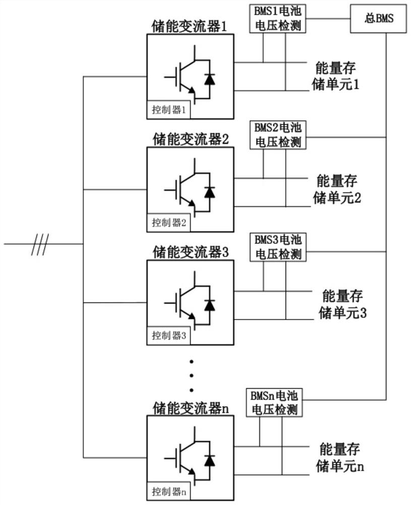
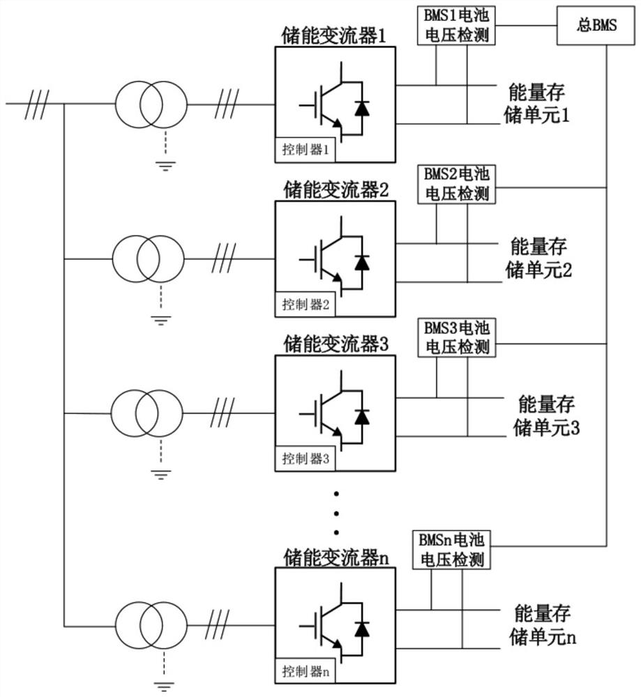
technical field [0001] The present application relates to the technical field of power electronics, in particular to an energy storage system and a carrier synchronization method thereof. Background technique [0002] In the existing energy storage system, when multiple machines are connected in parallel, each PCS (Power Conversion System, energy storage converter) only receives the start and stop commands of the host computer, and operates independently. Circulation is generated between each PCS, which increases the loss of the energy storage system and generates large electromagnetic interference at the same time. Devices connected to the PCS with electrical signals, such as BMS (Battery Management System, battery management system), will not work properly due to interference, affecting the operation of the entire system. [0003] figure 1 It is an existing energy storage system without an isolation transformer, and there is no mutual isolation between the PCSs, which is...

Claims


Application Information

Patent Timeline
Patent Type & Authority Applications(China)
IPC IPC(8): H02J3/32H02J13/00
CPCH02J3/32H02J13/00007Y04S10/14Y02E60/00Y04S40/121
Inventor 周党生董闯吴志猛刘永桥廖荣辉冯欢
Owner SHENZHEN HOPEWIND ELECTRIC CO LTD
Learn More