
Separated cable bridge for building installation

A cable tray, separate technology, applied in the direction of electrical components, etc., can solve the problems of difficult cable, take out, maintenance, etc., and achieve the effect of simple use, good maintenance effect, and easy operation.

Inactive Publication Date: 2021-01-22
王跃珍
View PDF1 Cites 0 Cited by
  • Summary
  • Abstract
  • Description
  • Claims
  • Application Information

AI Technical Summary

Problems solved by technology

However, since there are often many cables laid in the bridge frame, when a power failure occurs and a single cable needs to be maintained, it is difficult to take out the cables for maintenance due to the stacking of cables

Method used

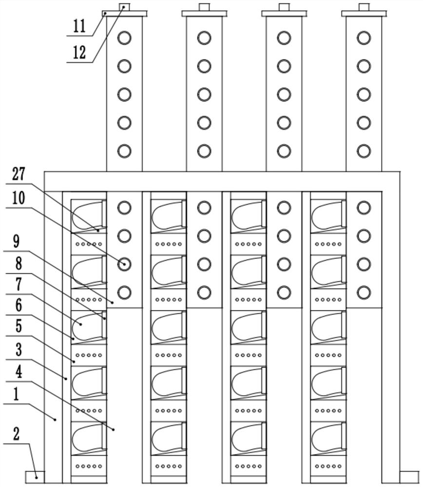

Image

  • Separated cable bridge for building installation
  • Separated cable bridge for building installation
  • Separated cable bridge for building installation

Examples


Embodiment 1

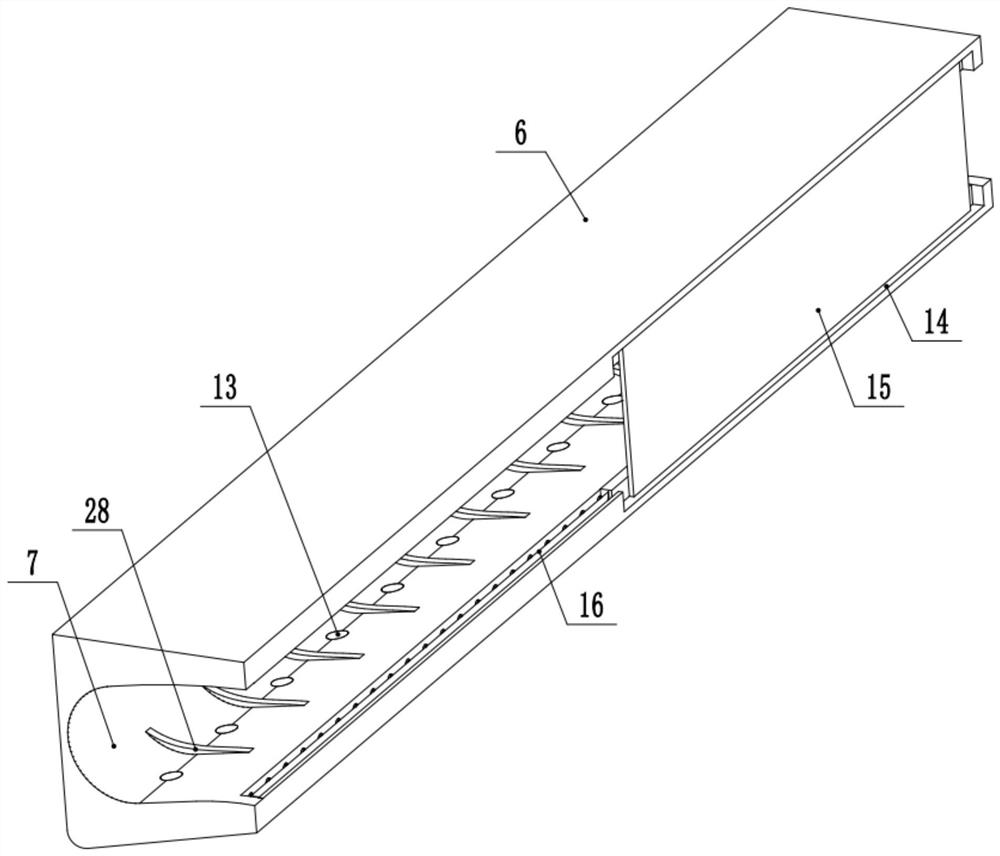
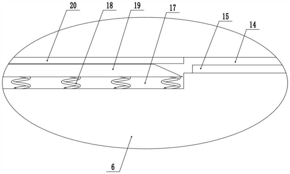
[0025] see Figure 1-5 , a detached cable bridge for building installation, comprising a bridge body 1, both sides of the bottom of the bridge body 1 are fixedly connected with legs 2, the bottom of the bridge body 1 is open, and the interior of the bridge body 1 is fixedly connected to a plurality of inner The mounting frame 3 is provided with a vertical channel 4 between every two adjacent internal mounting frames 3, and a plurality of fixed covers 5 are fixedly connected in the internal mounting frame 3, and a cable placement seat is placed on the top of each fixed cover 5 6. There is a cable placement groove 7 in the cable placement seat 6, and a limit blocking device 8 is provided on the side of the cable placement seat 6 close to the vertical passage 4. The cable placement groove 7 communicates with the vertical passage 4, and the vertical passage 4 A discharge cover 9 is provided, the discharge cover 9 penetrates the top end of the bridge body 1, and the end of the disc...

Embodiment 2

[0031] see Figure 1-5 , the other content of this embodiment is the same as that of Embodiment 1, the difference is that: the bottom end of the cable placement seat 6 is provided with a plurality of first bottom grooves 13, and the top end of the fixed cover 5 is provided with a plurality of first bottom grooves 13. The first through hole 21 corresponding to the groove 13, the two ends of the fixed cover 5 are provided with a plurality of second through holes 22, and the lower part of the side of the fixed cover 5 close to the vertical channel 4 is provided with a side groove 23, the first through hole 21 , the second through hole 22 and the side groove 23 are all in communication with the inside of the fixed cover 5 .

[0032] The bottom of the cable placement groove 7 is fixed with a plurality of protruding ribs 28 , and the plurality of protruding ribs 28 are spaced apart from the plurality of first bottom grooves 13 . The protruding ribs 28 are used to separate the first...


PUM


Abstract

The invention discloses a separated cable bridge for building installation, and relates to the technical field of building installation. The separated cable bridge comprises a bridge body, a verticalchannel is arranged between every two adjacent inner installation frames, a plurality of fixing covers are fixedly connected in the inner installation frames, and a cable placing seat is placed at thetop end of each fixing cover; a cable placing groove is formed in the cable placing seat, a limiting blocking device is arranged on the side, close to the vertical channel, of the cable placing seat,a discharging cover is arranged in the vertical channel, the discharging cover penetrates through the top end of the bridge body, and the end of the discharging cover is connected with a negative pressure device. Through the arrangement of the cable placing seats, cable placing can be realized, according to the invention independent taking and placing can be realized through the vertical channels, installed cables can be limited by setting the limiting blocking devices, textile cables fall out of the cable placing grooves, ventilation and drainage of the interiors of the cable placing seats can be realized through the arrangement of the fixing covers and the discharging covers, and the purposes of moisture prevention and heat dissipation are achieved.

Description

technical field [0001] The invention relates to the technical field of building installation, in particular to a separate cable tray for building installation. Background technique [0002] Cable trays are divided into trough type, tray type, ladder type, grid type and other structures, and are composed of brackets, supporting arms and installation accessories. The bridge frame in the building can be erected independently or attached to various buildings and pipe gallery supports. It should reflect the characteristics of simple structure, beautiful appearance, flexible configuration and convenient maintenance. All parts need to be galvanized and installed in the building. An open-air bridge. The full name of the rigid structure system with close support cables composed of trough-type, tray-type or step-type straight sections, bends, tees, cross components, brackets, hangers, etc. [0003] In the Chinese utility model patent document with the publication number CN209389615U...

Claims


Application Information

Patent Timeline
IPC IPC(8): H02G3/04H02G3/03
CPCH02G3/03H02G3/0406H02G3/045
Inventor 王跃珍
Owner 王跃珍
Learn More