Nuclear Reactor Detector Assembly Removal Device

A detector assembly and nuclear reactor technology, which is applied in the fields of reactor fuel elements, reactors, nuclear engineering, etc., can solve the problems of undiscovered detector assembly removal and replacement equipment, etc., to achieve neat arrangement, reduce radiation dose, and improve reliability. sexual effect

Active Publication Date: 2022-04-01
NUCLEAR POWER INSTITUTE OF CHINA
View PDF13 Cites 0 Cited by
  • Summary
  • Abstract
  • Description
  • Claims
  • Application Information

AI Technical Summary

Problems solved by technology

[0004] The third-generation nuclear power plants of AP1000 and EPR are still in the construction stage, and no equipment for dismantling and replacing detector components has been found.

Method used


Image

  • Nuclear Reactor Detector Assembly Removal Device
  • Nuclear Reactor Detector Assembly Removal Device
  • Nuclear Reactor Detector Assembly Removal Device

Examples


Embodiment 1

[0100] see Figure 14-Figure 17 As shown, the nuclear reactor detector assembly dismantling device consists of the following components in a modularized combination,

[0101] Detector assembly gripper 1, large and small cart assembly 2, shearing and winding device 3, visual alignment device 4, monitoring device 5, high-placement storage container and storage rack 6; among them,

[0102] The large and small cart assembly 2 is arranged in the nuclear reactor building and is located directly above the detector assembly; the large and small cart assembly 2 includes a Y-direction moving cart 202 and an X-direction moving cart 204, and the cart 204 is assembled on the cart 202;

[0103] The detector assembly gripper 1 is arranged on the upper top surface of the trolley 204. The detector assembly gripper 1 includes an outer cylinder assembly 105 whose longitudinal axis is along the Z direction, and a grabbing assembly 104 that moves up and down along the outer cylinder assembly 105; ...

Embodiment 2

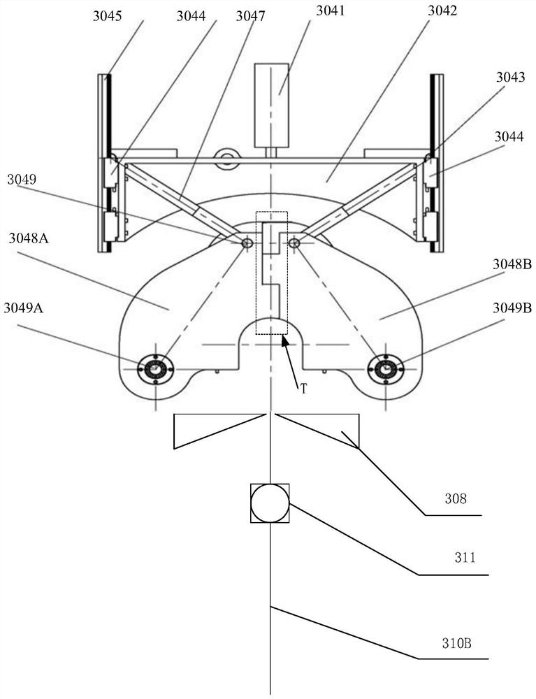
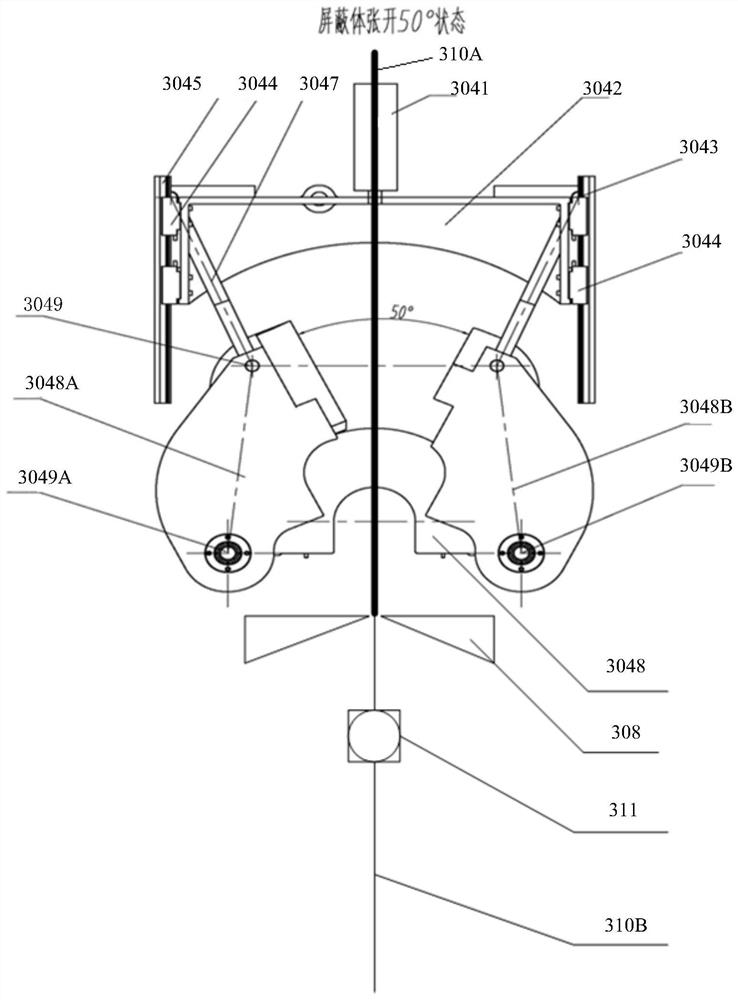
[0138] On the basis of the above-mentioned embodiment, as figure 1 , figure 2 shown,

[0139] like figure 1 , figure 2 Schematic side view of shielding structure for dismantling of nuclear reactor detector assemblies.

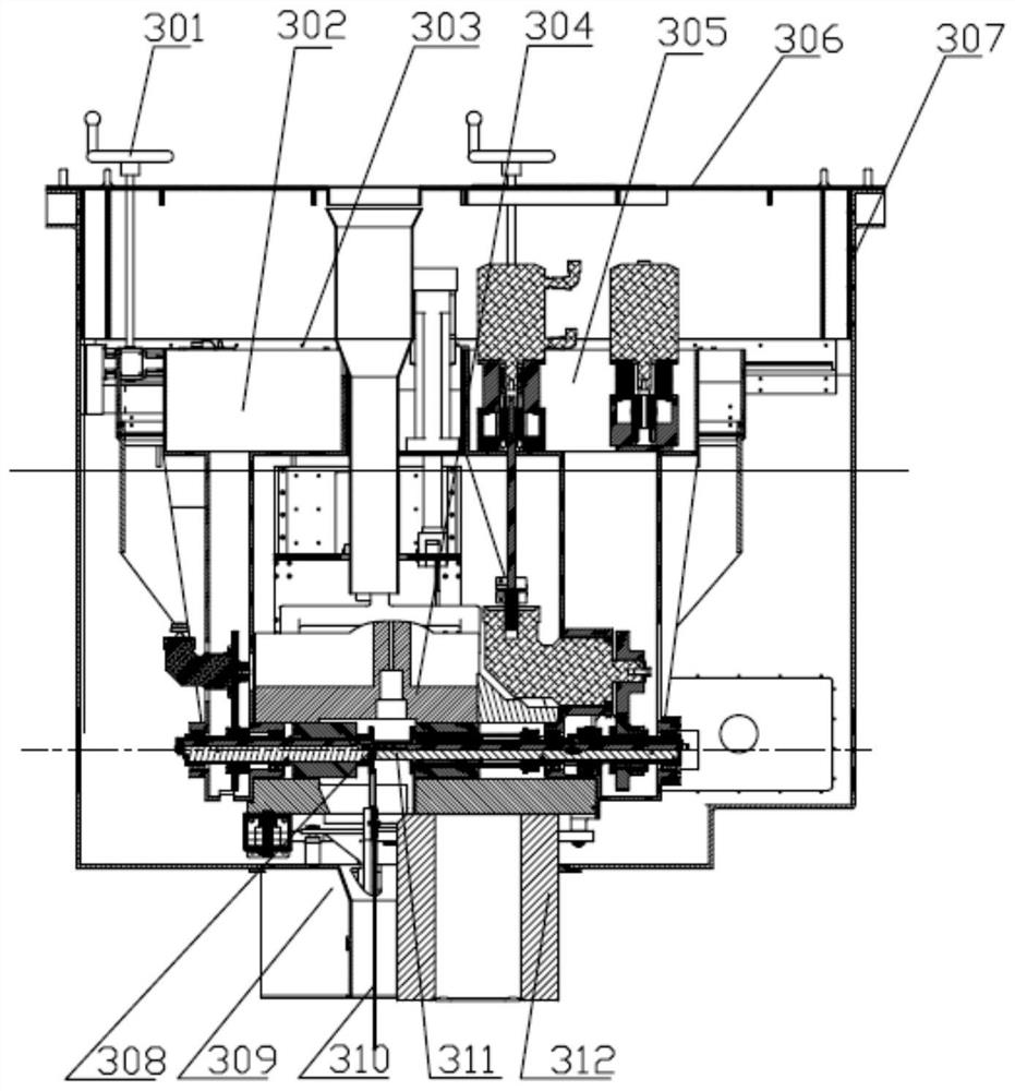
[0140] figure 1 and figure 2 The shielding structure shown is image 3 Shield structure 304 in .

[0141] The following front and back refer to the direction facing the legend paper as shown in the figure and the direction facing away from the paper.

[0142] Shielding structure, including:

[0143] The left shield body 3048A, the right shield body 3048B, the left shield shaft 3049A, and the right shield shaft 3049B; The shaft 3049A and the right shielding shaft 3049B are at the same level. The distance between the left shielding shaft 3049A and the right shielding shaft 3049B must ensure that the left shielding body 3048A rotates to the right around the left shielding shaft 3049A, and the right shielding body 3048B rotates around the right shieldin...


PUM


Abstract

The invention discloses a device for dismantling a nuclear reactor detector assembly. The device first uses the large and small car components to roughly position above the detector component to be removed, and then uses the vision centering device to finely position it directly above the detector component to be removed, and then lifts the gripper of the detector component to the large and small car components, and The detector assembly is pulled out from the internal components of the pile to a predetermined height, the shearing and winding device cuts the detector assembly, and the low-level section is hoisted by the detector assembly gripper under the cooperation of the crane and stored in the low-level container; The unwinding section is wound into multi-layer coils by a shearing and winding device and stored in a temporary storage container; after four full storages, the whole is transferred to a high-volume storage container; after all dismantling is completed, the high-amplification storage container is transferred to in spent fuel pools. The equipment has good reliability, high efficiency, simple operation and good radiation protection performance.

Description

technical field [0001] The invention relates to the technical field of dismantling of reactor equipment, in particular to a main shaft translation winding mechanism for dismantling a nuclear reactor detector assembly and a method of use. Background technique [0002] The detectors used in the core measurement system of the second-generation and second-generation pressurized water reactor nuclear power plants are divided into thermocouples for temperature measurement and neutron flux detectors for flux measurement. The thermocouple is introduced from the top cover of the pressure vessel, guided by the thermocouple column assembly, and positioned at the specified measuring point. The lower end of the thermocouple is located at the exit of the upper core plate. The flux detector is introduced from the bottom head of the pressure vessel, and is guided through the instrument casing and the finger casing when necessary, and enters the guide pipe inside the fuel assembly at the spe...

Claims


Application Information

Patent Timeline
Patent Type & Authority Patents(China)
IPC IPC(8): G21C19/02G21C19/105G21C19/20
CPCG21C19/02G21C19/105G21C19/207Y02E30/30
Inventor 安彦波李娜杨其辉余志伟黄宗仁湛卉张翼王尚武熊思勇曹锐罗英钟元章刘昌文陈书华王炳炎
Owner NUCLEAR POWER INSTITUTE OF CHINA
Why Eureka
Try Eureka