Method for measuring movable pulley positioning precision in ship lifting system

A lifting system and positioning accuracy technology, which is applied in the field of measurement of the positioning accuracy of the moving pulley in the ship lifting system, can solve problems such as the inability to accurately measure the parallelism and symmetry of the moving pulley, achieve stable take-off and landing, simple operation, and ensure installation and positioning accuracy Effect

Active Publication Date: 2021-01-22
HUDONG ZHONGHUA SHIPBUILDINGGROUP
View PDF13 Cites 0 Cited by
  • Summary
  • Abstract
  • Description
  • Claims
  • Application Information

AI Technical Summary

Problems solved by technology

[0003]In the original construction process, due to the lack of suitable tooling, it was impossible to accurately measure the parallelism and symmetry of the movable pulley installed on the base of the hydraulic unit

Method used


Image

  • Method for measuring movable pulley positioning precision in ship lifting system
  • Method for measuring movable pulley positioning precision in ship lifting system
  • Method for measuring movable pulley positioning precision in ship lifting system

Examples


Embodiment 1

[0040] Embodiment 1, the method for measuring the positioning accuracy of the movable pulley in the ship lifting system of the present invention specifically includes the following steps:

[0041] S1, install a three-dimensional steel wire debugging device 24 on the bulkhead near the hydraulic press plunger 18, and place a temporary bracket 20 on the ground at the other opposite side.

[0042] Specifically, a support plate 19 is welded on the bulkhead near the plunger 18 of the hydraulic press, and the three-dimensional steel wire debugging device is fixed on the support plate 19 .

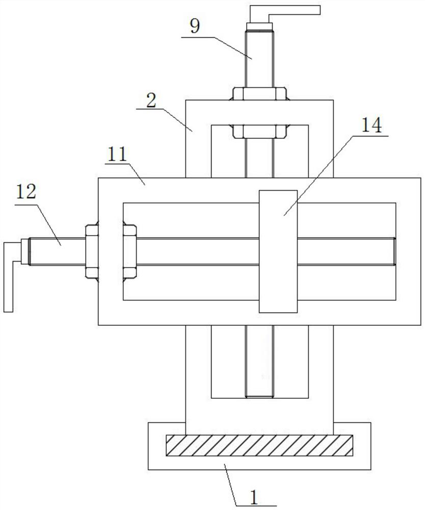
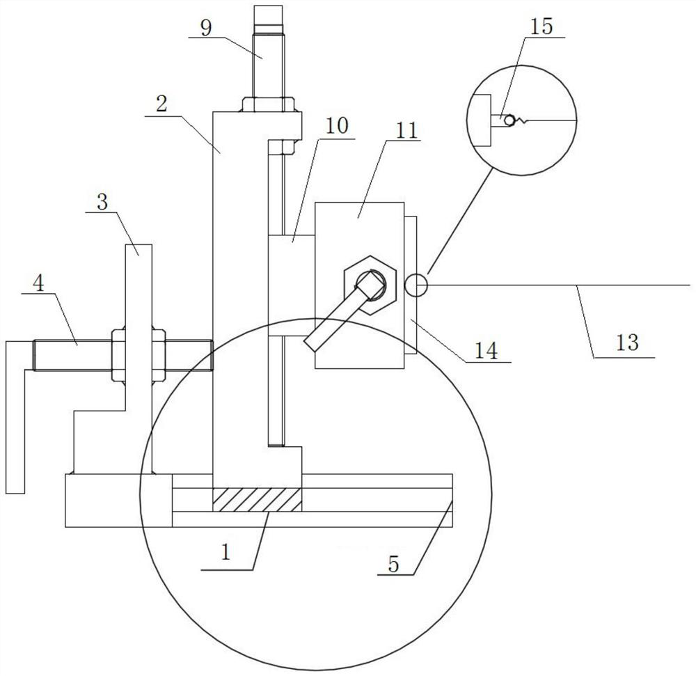
[0043] The three-dimensional steel wire debugging device includes a base 1, a longitudinal frame 2 movably arranged in the base 1, a support seat 3 fixed on the upper end surface of the base 1, and a support seat 3 arranged on the support seat 3 to adjust the longitudinal frame 2 on the base 1. The first adjustment mechanism 4 that moves in the length direction.

[0044] A rail groove 5 is opened...

Embodiment 2

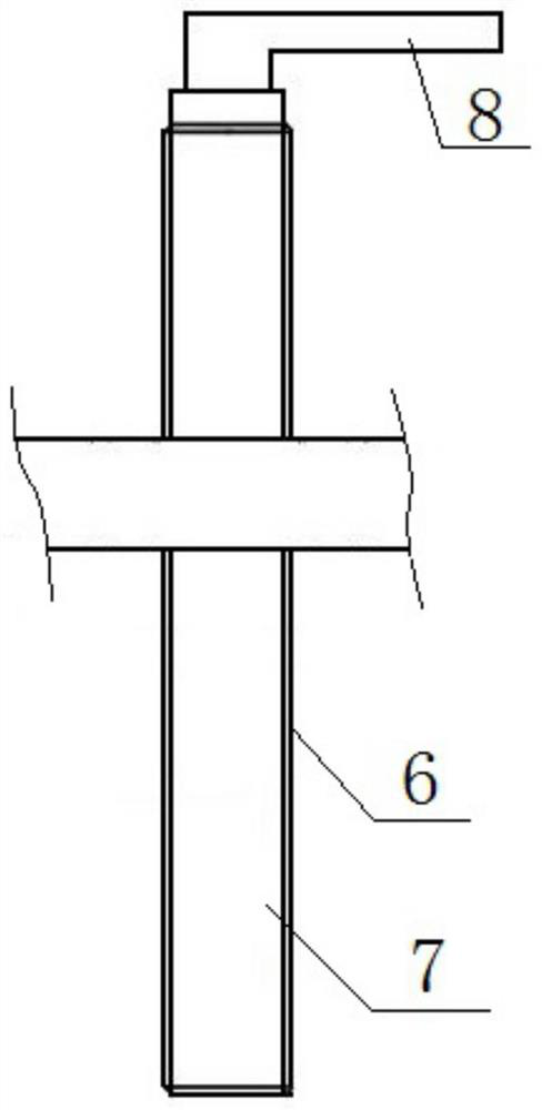
[0057] Embodiment 2, this embodiment is basically the same as Embodiment 1, the specific difference is that the first adjustment structure 4, the second adjustment mechanism 9 and the third adjustment mechanism 12 of the three-dimensional steel wire debugging device have the same structure, and all include nuts 23 , the screw rod 7 threadedly fixed with the nut 23, and the handle 8 fixed at the end of the screw rod 7.

[0058] Specifically, the nut 23 of the first adjustment mechanism 4 is welded and fixed on the front and rear end faces of the support base 19, and its screw rod 7 passes through the support base 3 and is threaded in the nut 23. By rotating the handle of the first adjustment mechanism 4, The screw rod of the first adjustment mechanism 4 can push the longitudinal frame 2 to slide in the guide rail groove 5 .

[0059] The nut of the second adjustment mechanism 9 is welded and fixed on the upper and lower end surfaces of the upper beam of the longitudinal frame 2,...


PUM


Abstract

The invention discloses a method for measuring the positioning precision of a movable pulley in a ship lifting system. The method specifically comprises the following steps: installing a three-dimensional steel wire debugging device on a bulkhead, and placing a temporary bracket on the ground at the other opposite side; fixing one end of a steel wire rope on the three-dimensional steel wire debugging device, and hanging a heavy object at the other end to be supported on the temporary bracket; measuring whether the distances from the top of the movable pulley to the steel wire rope are equal atdifferent positions during dynamic operation, and if so, determining that the parallelism of the movable pulley meets the requirement; adjusting the three-dimensional steel wire debugging device to move the steel wire rope to the side of a hydraulic press guide rail; and measuring whether the distances from the side surfaces of the movable pulley to the steel wire rope at different positions during dynamic operation are equal, and if so, determining that the symmetry of the movable pulley meets the requirement. According to the invention, the parallelism and the symmetry degree of the movablepulley can be rapidly measured, and the mounting and positioning precision of the movable pulley is effectively ensured, so that the stable and safe lifting of the lifting platform is ensured.

Description

technical field [0001] The invention relates to the technical field of ship building, in particular to a method for measuring the positioning accuracy of a movable pulley in a ship lifting system. Background technique [0002] The stern of the ship is equipped with a hydraulically driven lifting platform system. The lifting platform system drives each set of fixed pulleys through the movable pulley on the hydraulic unit, so that the lifting and landing effect of the platform is achieved by the wire rope traction. The driving structure of the hydraulic unit consists of two plungers and four guide rails. The hydraulic plunger reciprocates in the guide rails. The hydraulic plunger is connected to the movable pulley through a wire rope, and the movable pulley is connected to the fixed pulley through a wire rope to realize the retraction and release of the wire rope and wire rope. Achieve the lifting effect of the lifting platform. [0003] It turned out that during the construc...

Claims


Application Information

Patent Timeline
Patent Type & Authority Applications(China)
IPC IPC(8): G01B21/00G01B21/22
CPCG01B21/00G01B21/22
Inventor 盛健周彦成
Owner HUDONG ZHONGHUA SHIPBUILDINGGROUP
Why Eureka
Try Eureka