Knitted garment manufacturing system

A garment manufacturing and knitting technology, which is applied in the field of knitted garment manufacturing system, can solve the problems of scattered finished cloth, difficult winding, and cloth wrinkle, etc., and achieve the effect of good fixing effect, convenient inspection, and easy knitting

Active Publication Date: 2021-01-22
浙江晞尔波针织有限公司
View PDF7 Cites 2 Cited by
  • Summary
  • Abstract
  • Description
  • Claims
  • Application Information

AI Technical Summary

Problems solved by technology

[0003] In the patent application number 202010753579.4, "a computerized flat knitting machine with thread breakage detection" is mentioned. This device has the function of preventing the yarn in the computerized flat knitting machine from continuing to run after the yarn is broken when the thread is broken, reducing the waste of yarn. , and at the same time reduce the effect of the probability of damage to the parts of the machine body, but after the weaving of the device is completed, the finished cloth is scattered under the device, it is difficult to find the problem of knitting on the surface of the cloth, and the cloth is wrinkled and difficult to rewind
At the same time, there is no special device for feeding materials to knitting equipment, and there is room for improvement. For the knitting device part of the present invention, the applicant applied for a separate invention patent application for protection on the same day. This application is mainly for protection of the overall manufacturing system

Method used


Image

  • Knitted garment manufacturing system
  • Knitted garment manufacturing system
  • Knitted garment manufacturing system

Examples


Embodiment

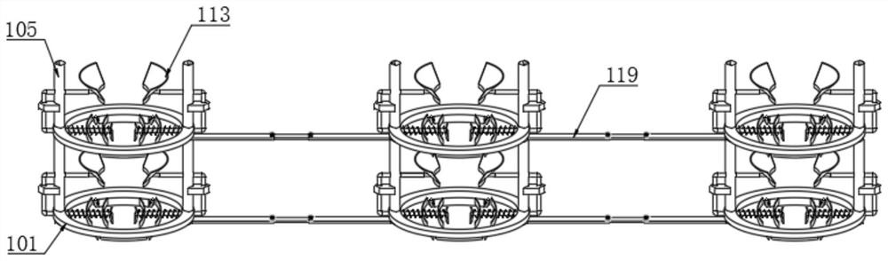
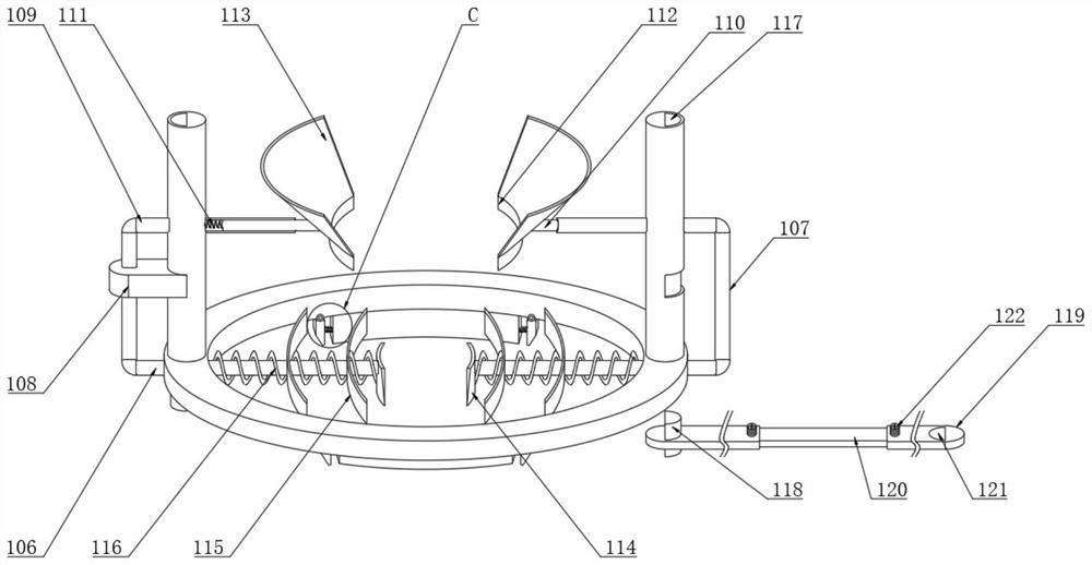
[0041] Example: such as Figure 1-4 A knitted garment manufacturing system shown includes a feeding device 100 and a manufacturing device 200. After the yarn is fed by the feeding device 100, the manufacturing device 200 performs knitting. The feeding device 100 includes a bottom ring 101, and the two ends of the bottom surface of the bottom ring 101 are All positions are welded with clamping plates 102, and the bottom ring 101 is hinged with rubber clips 103 near both ends of the clamping plate 102. Both ends of the top surface of 101 are welded with support columns 105, and the two ends of the bottom ring 101 are located at the bottom of the support column 105, and a bottom rod 106 is installed through it. The top of the bottom rod 106 is welded with a vertical rod 107, and the middle part of the vertical rod 107 is socketed There is a magnet 108, and a guide tube 109 is welded on the top of the vertical rod 107, and the guide tube 109 moves through the middle of the support...


PUM


Abstract

The invention discloses a knitted garment manufacturing system. A feeding device comprises a bottom ring; rubber clamping blocks are hinged to the positions, close to the two ends of a clamping plate,of the bottom ring; supporting columns are welded to the two ends of the top face of the bottom ring; vertical rods are welded to the top ends of the bottom rods; guide pipes movably penetrate through the middles of the supporting columns; the ends, away from the vertical rods, of the guide pipes are connected to one ends of drawing rods in a sleeving mode; one ends, located in the guide pipes, of the drawing rods are spot-welded to one end of a retaining spring; an arc-shaped rubber plate is bonded to the ends, away from the retaining spring, of the drawing rods; a guide plate is bonded to the top end of the arc-shaped rubber plate; shifting pieces are bonded to the ends, located in the bottom ring, of bottom rods; the outer sides of the bottom rods are sleeved with rubber supporting strips; the shifting pieces, the rubber supporting strips and the adjacent rubber supporting strips are connected through sleeving springs; connecting positioning blocks are welded to the positions, corresponding to the connecting positioning holes, of the bottom end of the bottom ring; the opposite ends of two extension pipes are sleeved with the two ends of extension rods respectively; and butt joint holes are formed in the positions, corresponding to the connecting positioning blocks, of the extension pipes.

Description

technical field [0001] The invention relates to the technical field of textiles, in particular to a knitted garment manufacturing system. Background technique [0002] Knitting refers to the process of using knitting needles to form loops of various raw materials and yarns, and then connecting them into knitted fabrics through stringing. Knitted fabrics are soft in texture, have good wrinkle resistance and air permeability, and have greater extensibility and elasticity. They are comfortable to wear. Knitting is divided into two categories: hand knitting and machine knitting. Knitting production is divided into two categories: weft knitting and warp knitting. The computerized flat knitting machine is a double-needle plate latch weft knitting machine. [0003] In the patent application number 202010753579.4, "a computerized flat knitting machine with thread breakage detection" is mentioned. This device has the function of preventing the yarn in the computerized flat knitting ...

Claims


Application Information

Patent Timeline
Patent Type & Authority Applications(China)
IPC IPC(8): D04B15/42D04B15/56D04B15/90D04B35/00D04B35/22D04B35/26D06H3/08
CPCD04B15/42D04B35/26D04B35/22D04B35/00D04B15/90D04B15/56D06H3/08
Inventor 韩桂贞
Owner 浙江晞尔波针织有限公司
Why Eureka
Try Eureka