Eureka AIR delivers breakthrough ideas for toughest innovation challenges, trusted by R&D personnel around the world.

T-shaped precast beam hoisting device

A hoisting device and prefabricated beam technology, which is applied in the direction of transportation and packaging, load hanging components, etc., can solve the problems of wire rope rotation, limit plate deformation, and difficult two-set clamp connection, etc., to achieve the effect of being conducive to lifting and lifting stability

Inactive Publication Date: 2021-01-22
齐嘉蕾
View PDF0 Cites 0 Cited by
  • Summary
  • Abstract
  • Description
  • Claims
  • Application Information

AI Technical Summary

Problems solved by technology

[0003] When the current T-shaped prefabricated beam is hoisted, the bottom of the T-shaped beam is clamped by the clamp, and the two clamps are moved relatively by the force of the wire rope, and then the two clamps are limited by the limit plate, then the T-shaped beam is in It is suspended between two fixtures to realize the lifting of the T-shaped beam. The two right angles of the T-shaped beam are not limited and stressed. When lifting, it is easy to cause the deformation of the limiting plate, and it will pass through directly when lifting. The steel wire rope of the hoisting device lifts the T-beam. If the T-beam deviates before lifting, it is difficult to adjust to a balanced position. When lifting, it is easy to cause the wire rope to rotate, resulting in a decrease in the stability of the lifting. When the lifting fixture is not used The two sets of fixtures are in a separate state, it is difficult to connect the two sets of fixtures, and it is inconvenient to take and store

Method used


Image

  • T-shaped precast beam hoisting device
  • T-shaped precast beam hoisting device
  • T-shaped precast beam hoisting device

Examples


Embodiment Construction

[0026] In order to make the technical means, creative features, goals and effects achieved by the present invention easy to understand, the present invention will be further described below in conjunction with specific embodiments.

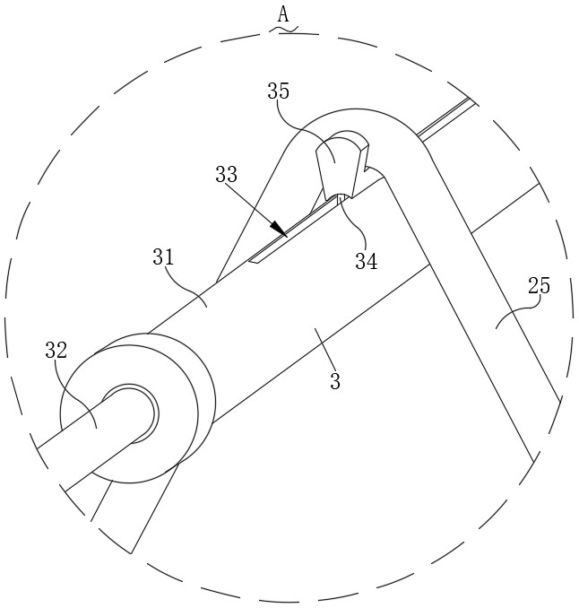
[0027] like Figure 1-Figure 9As shown, a T-shaped prefabricated beam hoisting device according to the present invention includes a prefabricated beam body 1, two sets of clamping mechanisms 2, a lifting mechanism 3, a suspension mechanism 4, a reinforcement mechanism 5, and a storage mechanism 6. The prefabricated beam body The two ends of 1 are respectively clamped by two sets of clamping mechanisms 2 with an "X"-shaped structure, and the top ends of the two sets of clamping mechanisms 2 are connected by the lifting mechanism 3 for connecting two clamping mechanisms. The surface center of the lifting mechanism 3 of the clamping mechanism 2 is rotatably connected to the suspension mechanism 4 connected to the lifting device, and the opposite side...


PUM


Abstract

The invention relates to the technical field of precast beam hoisting, in particular to a T-shaped precast beam hoisting device which comprises a precast beam body, two sets of clamping mechanisms, alifting mechanism, a suspension mechanism, reinforcing mechanisms and a storage mechanism. The two sides of the precast beam body are clamped through the clamping mechanisms with the X-shaped sections, the two clamping mechanisms are connected through the lifting mechanism, the lifting mechanism can be adjusted, and the lifting mechanism can be adjusted according to the inclined direction if it isfound that the precast beam is unbalanced during lifting, so that the precast beam is lifted more stably, hoisting is facilitated, and during hoisting, the hoisting device can be connected with the suspension mechanism on the lifting mechanism to realize hoisting. The reinforcing mechanisms are arranged on the opposite side faces of the two sets of clamping mechanisms, the two sets of clamping mechanisms can be clamped through the two reinforcing mechanisms after it is determined that the precast beam is balanced before hoisting, and inclination of the clamping mechanisms is avoided; and thestorage mechanism is arranged between the two clamping mechanisms, carrying is facilitated, and operation is easy.

Description

technical field [0001] The invention relates to the technical field of prefabricated beam hoisting, in particular to a T-shaped prefabricated beam hoisting device. Background technique [0002] Prefabricated beams are prefabricated in factories, and then transported to the construction site to be installed and fixed according to the design requirements. T-shaped beams refer to beams with a T-shaped cross-section. The protruding part on both sides is called the flange, and the middle part is called the beam rib (or web). Because it is equivalent to digging out the concrete in the tension zone of the rectangular beam that does not play a role in the flexural strength. Although the bending strength of the original rectangle is exactly the same, it can not only save concrete, but also reduce the weight of the component and improve the spanning ability. [0003] When the current T-shaped prefabricated beam is hoisted, the bottom of the T-shaped beam is clamped by the clamp, and...

Claims


Application Information

Patent Timeline
Patent Type & Authority Applications(China)
IPC IPC(8): B66C1/14
CPCB66C1/14
Inventor 齐嘉蕾
Owner 齐嘉蕾
Why Eureka
Eureka Blog
Learn More