Drill point feeding device and equipment

A technology of feeding device and drill pin, which is applied to conveyors, conveyor objects, transportation and packaging, etc., can solve the problems of increasing production costs, increasing the frequency of drilling pins, and increasing labor costs.

Active Publication Date: 2021-01-22
CAMELOT QINGYUAN HYTEC TECH INVESTMENT
View PDF9 Cites 0 Cited by
  • Summary
  • Abstract
  • Description
  • Claims
  • Application Information

AI Technical Summary

Problems solved by technology

In the case of a certain length of the conveyor belt, the number of material boxes transported on the conveyor belt is limited, so that the conveyor belt can store about 400 drill needles, and it takes about 30-40 minutes for the operator to retract and release the drill needles once, so that The feeding frequency of drill needles increases, and frequent feeding is required, which increases labor costs and thus increases production costs

Method used


Image

  • Drill point feeding device and equipment
  • Drill point feeding device and equipment
  • Drill point feeding device and equipment

Examples


Embodiment Construction

[0026] In order to facilitate the understanding of the present invention, the present invention will be described more fully below with reference to the associated drawings. Preferred embodiments of the invention are shown in the accompanying drawings. However, the present invention can be embodied in many different forms and is not limited to the embodiments described herein. On the contrary, the purpose of providing these embodiments is to make the disclosure of the present invention more thorough and comprehensive.

[0027] It should be noted that when an element is referred to as being “fixed” to another element, it can be directly on the other element or there can also be an intervening element. When an element is referred to as being "connected to" another element, it can be directly connected to the other element or intervening elements may also be present. The terms "vertical," "horizontal," "left," "right," and similar expressions are used herein for purposes of ill...


PUM


Abstract

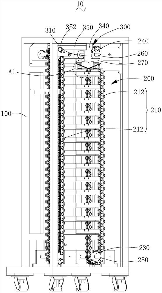
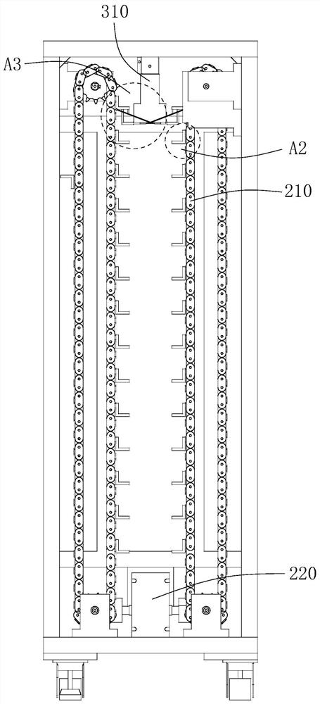
The invention provides a drill point feeding device and equipment. The drill point feeding device comprises a mounting bracket and a conveying mechanism. The conveying mechanism comprises a conveyingassembly, a rotating motor, a driving wheel, a driven wheel, a first connecting rod, a second connecting rod and a plurality of material pieces, wherein the conveying assembly is arranged on the driving wheel and the driven wheel in a sleeving manner, the plurality of material pieces are connected to the outer side of the conveying assembly, and each material piece is provided with a bearing face.The bearing surface of each material piece is used for bearing a material box filled with a drill point. The material pieces are arranged on the side edges of the conveying assembly. When the material boxes are placed on the bearing faces of the material pieces, the bottom faces of the material boxes abut against the bearing faces, the side faces of the material boxes are parallel to the conveying assembly, and the number of the material boxes placed on the conveying assembly is increased while it is guaranteed that the material boxes are horizontally placed, so that the number of the drill pints placed on the conveying assembly is increased, the drill point loading period of the drill points on the conveying assembly is prolonged, and the loading frequency of the drill points is reduced.

Description

technical field [0001] The invention relates to the technical field of drill grinding, in particular to a drill feeding device and equipment. Background technique [0002] With the development of electronic technology, a plurality of different types of electronic components are integrated through a PCB (Printed Circuit Board, printed circuit board), which is convenient for reducing the size of the electronic equipment. Wherein, each component on the PCB is installed through drilling holes thereon, and then each component is fixed on the PCB by welding. However, due to the relatively large demand for the drill pins required for PCB drilling, they need to be mass-produced through grinding machines to meet the demand for drill pins. [0003] The grinding speed of the traditional grinding machine is about 500-900 pieces / hour. The conveyor belt in the grinder is used to transport the material box with multiple drill needles. The material box is square on the conveyor belt, that ...

Claims


Application Information

Patent Timeline
Patent Type & Authority Applications(China)
IPC IPC(8): B65G47/82B65G23/04B65G17/26
CPCB65G17/26B65G23/04B65G47/82
Inventor 刘仁和朱建华
Owner CAMELOT QINGYUAN HYTEC TECH INVESTMENT
Why Eureka
Try Eureka