


Quick Research
Generate reliable direction feasibility study reports for your R&D in just a few steps.

Technical Q&A
Discover and master advanced knowledge NOW. Basics, ideas, possibilities, all at once.

Find Solutions
As an expert in R&D theories, this can generate solutions to your technical problems instantly.

Evaluate Feasibility
Analyze your overall solution with one click, know your potential R&D risks in advance.

Monitor Landscape
Get weekly tech updates, stay abreast of the latest tech innovations and key insights.
Buckling mechanism of casting mold
A technology for casting molds and mold bodies, which is applied in the field of casting molds and can solve problems that affect the normal production of molds and are prone to cracks
- Summary
- Abstract
- Description
- Claims
- Application Information
AI Technical Summary
Problems solved by technology
Method used
Image

Examples
Embodiment 1
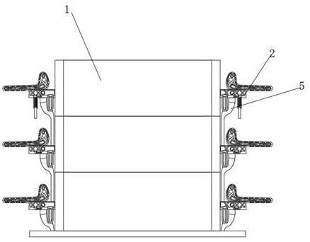
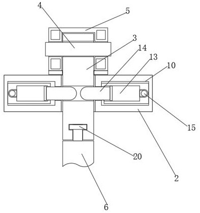
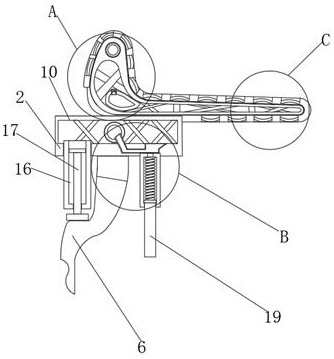
[0022] see Figure 1-3 , a fastening mechanism for a casting mold, comprising three mold main bodies 1, characterized in that: both sides of the three mold main bodies 1 are fixedly connected with a support plate 2, and the surface of the support plate 2 is movably connected with a fixed rod 3, supporting The surface of the plate 2 is provided with a card slot suitable for the fixed rod 3, and the surface of the fixed rod 3 near the top is rotatably connected with the movable shaft 4, and the surface of the movable shaft 4 is fixedly connected with an arc-shaped clamping rod 5, and the curved clamping rod 5 The surface of the fixed rod 3 is provided with an elastic rubber pad, and the arc-shaped clamping rod 5 is clamped with the surface of the support plate 2 through the elastic rubber pad, and the bottom end of the fixed rod 3 is movably connected with an arc-shaped strut 6 through a rotating shaft, and the arc-shaped strut 6 The bottom end is fixedly connected to the top su...
Embodiment 2
[0025] see Figure 4 , the inside of the support plate 2 is provided with a control chamber 10, the inside of the control chamber 10 and the inflatable chamber 7 are fixedly connected with a support frame 11, and the front shape of the support frame 11 is X-shaped, and the inside of the control chamber 10 and the inflatable chamber 7 are uniform. A shrinkable airbag 12 is provided, and the interior of the shrinkable airbag 12 is filled with lubricating oil, and a check valve is provided on the surface of the shrinkable airbag 12 .
[0026] The difference from Embodiment 1 is that the inside of the inflatable cavity 7 can be reinforced through the support frame 11 and the shrinkable air bag 12, and at the same time, it is ensured that the gas inside the inflatable cavity 7 can be squeezed and contracted after the gas is expanded by heat, thereby leaving a suitable space. space, cooperate with the support frame 11 to ensure the firmness of the arc clamping rod 5 as a whole.
Embodiment 3
[0028] see Figure 5-6 , the inner wall of the control chamber 10 is fixedly connected with a clamping sleeve 13, and the inner wall of the clamping sleeve 13 is movably connected with a clamping piston 14. The inside of the clamping sleeve 13 communicates with an air delivery tube 15, and the end of the air delivery tube 15 away from the clamping sleeve 13 communicates with the inside of the control chamber 10. The bottom surface of the support plate 2 is inlaid with a pressing sleeve 16, and the pressing sleeve The inner wall of the pipe 16 is movably connected with a pressing piston 17, and the bottom surface of the pressing piston 17 is movably connected with the upper surface of the arc-shaped strut 6, and the upper surface of the arc-shaped strut 6 is provided with a horizontal groove matching the pressing piston 17 to support The bottom surface of the plate 2 is inlaid with a buffer sleeve 18, and the inner wall of the buffer sleeve 18 is movably connected with a buffer...
PUM
 Abstract
Description
Claims
Application Information
 - R&D Engineer
- R&D Manager
- IP Professional
- Industry Leading Data Capabilities
- Powerful AI technology
- Patent DNA Extraction
Browse by: Latest US Patents, China's latest patents, Technical Efficacy Thesaurus, Application Domain, Technology Topic, Popular Technical Reports.
© 2024 PatSnap. All rights reserved.Legal|Privacy policy|Modern Slavery Act Transparency Statement|Sitemap|About US| Contact US: help@patsnap.com