


Quick Research
Generate reliable direction feasibility study reports for your R&D in just a few steps.

Technical Q&A
Discover and master advanced knowledge NOW. Basics, ideas, possibilities, all at once.

Find Solutions
As an expert in R&D theories, this can generate solutions to your technical problems instantly.

Evaluate Feasibility
Analyze your overall solution with one click, know your potential R&D risks in advance.

Monitor Landscape
Get weekly tech updates, stay abreast of the latest tech innovations and key insights.
Mixing device for preparing industrial enzyme preparation
A mixing device and enzyme preparation technology, which is applied in the direction of enzymology/microbiology devices, mixers, biochemical cleaning devices, etc., can solve the problems of affecting the mixing effect and swirl, and achieve the effect of improving the effect
- Summary
- Abstract
- Description
- Claims
- Application Information
AI Technical Summary
Problems solved by technology
Method used
Image


Examples
Embodiment 1
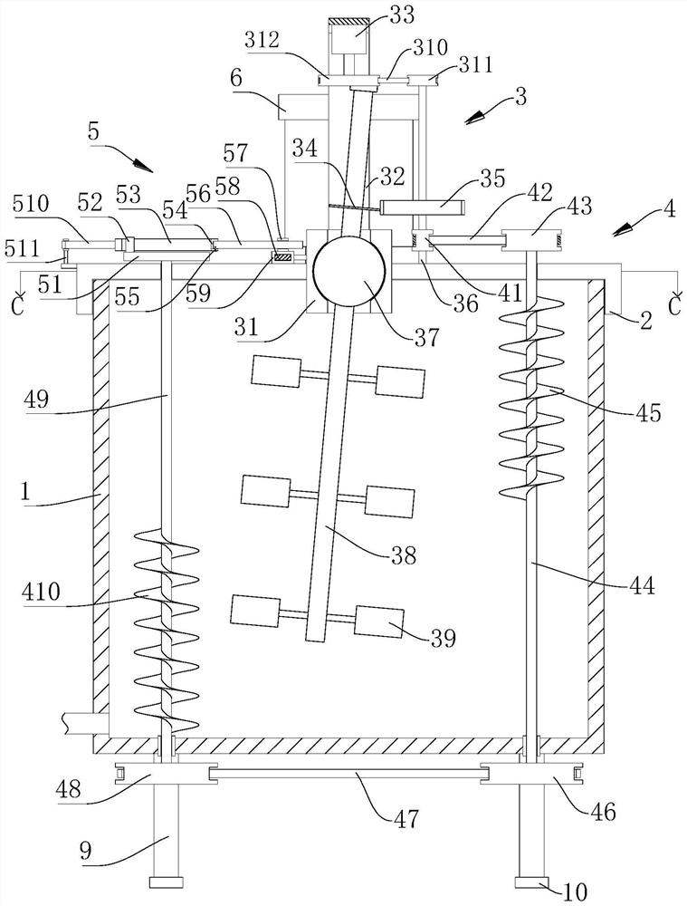
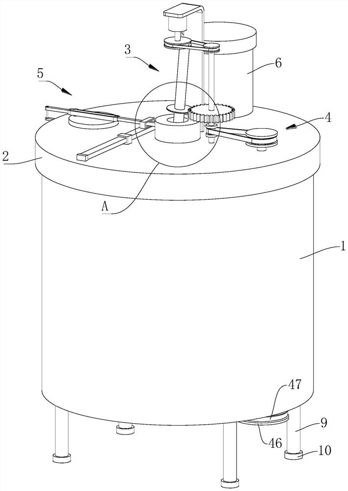
[0023]ReferenceFigure 1-7 , A mixing device for the preparation of industrial enzyme preparations, comprising a mixing box 1, a supporting foot 9 is fixedly installed on the lower end of the mixing box 1, the supporting foot 9 plays a role of supporting and fixing, and the lower end of the first supporting foot 9 is fixedly pasted with a cushion 10 The cushion 10 is composed of a rubber structure and has the effect of damping and buffering, and also has the effect of anti-skid, which improves the anti-skid effect of the bottom of the mixing box 1. The upper end of the mixing box 1 is screwed with a box cover 2, and the upper end of the box cover 2 is fixedly installed There is a main stirring element 3, which has the function of stirring and mixing. A container 6 is fixedly installed on the upper end surface of the box cover 2, and the container 6 is used to place the preparations to be added and mixed.
[0024]The main mixing element 3 includes a limiting sleeve 31, a mounting plate 3...
Embodiment 2
[0029]In the mixing process of different formulations, the formulations with different densities may be stratified during the mixing process. The denser formulations may settle at the bottom of the mixing box 1, and it is not easy to mix uniformly with the upper-layer formulations with lower density. For this reason, we propose this embodiment 2, refer toFigure 1-5 As another preferred embodiment of the present invention, on the basis of embodiment 1, an auxiliary stirring member 4 is fixedly installed inside the mixing box 1, and the auxiliary stirring member 4 includes a first pulley 41, a first belt 42, and a second pulley 43. The first inner shaft 44, the first conveying screw 45, the third pulley 46, the second belt 47, the fourth pulley 48, the second inner shaft 49 and the second conveying screw 410.
[0030]The first pulley 41 is fixedly installed in the middle of the connecting shaft 36. The rotation of the second gear 35 will drive the first pulley 41 to rotate through the co...
Embodiment 3
[0035]Referencefigure 1 andFigure 5-6As another preferred embodiment of the present invention, on the basis of embodiment 1 or embodiment 2, it further includes a feeding member 7. The upper end surface of the box cover 2 and located on the side of the restricting sleeve 31 is fixedly installed with a linkage member 5, the feeding member 7 is connected to the linkage member 5 in transmission. The linkage member 5 includes a turntable 51, a protrusion 52, a linkage frame 53, a bolt 55, a linkage rod 56, a socket block 57, a reciprocating rod 58, a mounting block 59, a fixed rod 510 and a mounting shaft 511 , The turntable 51 is fixedly installed on the end of the second inner shaft 49 that extends to the top of the cover 2, and the protrusion 52 is fixedly installed on the upper end surface side of the turntable 51. The rotation of the second inner shaft 49 drives the turntable 51 to rotate. Drive the protrusion 52 to rotate.
[0036]The linkage frame 53 is movably sleeved on the outsid...
PUM
 Abstract
Description
Claims
Application Information
 - R&D Engineer
- R&D Manager
- IP Professional
- Industry Leading Data Capabilities
- Powerful AI technology
- Patent DNA Extraction
Browse by: Latest US Patents, China's latest patents, Technical Efficacy Thesaurus, Application Domain, Technology Topic, Popular Technical Reports.
© 2024 PatSnap. All rights reserved.Legal|Privacy policy|Modern Slavery Act Transparency Statement|Sitemap|About US| Contact US: help@patsnap.com