Piping shaft optimization algorithm

An optimization algorithm and pipeline well technology, applied in calculation, computer-aided design, instrument, etc., can solve the problem of pipeline well optimization, which is rarely involved in research

Active Publication Date: 2021-01-19
TONGJI UNIV
View PDF4 Cites 2 Cited by
  • Summary
  • Abstract
  • Description
  • Claims
  • Application Information

AI Technical Summary

Problems solved by technology

However, there are few studies on the piping planning of building mechanical and electrical

Method used


Image

  • Piping shaft optimization algorithm
  • Piping shaft optimization algorithm
  • Piping shaft optimization algorithm

Examples


Embodiment 1

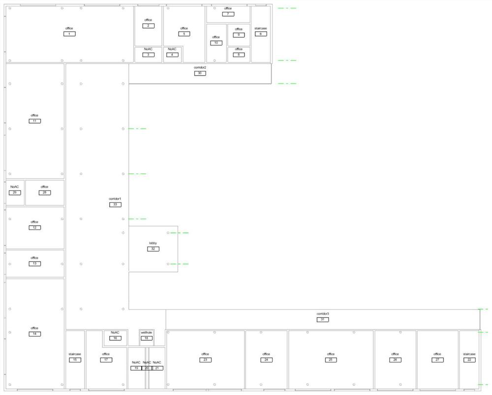
[0056] In this embodiment, the optimization of the air-conditioning pipe wells on the first floor of a certain building is carried out. The floor plan of the building is as figure 2 , the architectural drawing includes three types of rooms related to air-conditioning ducts: office, corridor, and wellhole. The name of the terminal equipment includes the floor number, room number, room function, and equipment number (such as 1F: 18wellhole_1).

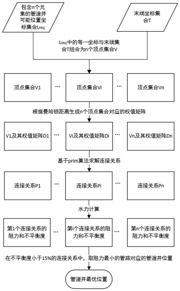
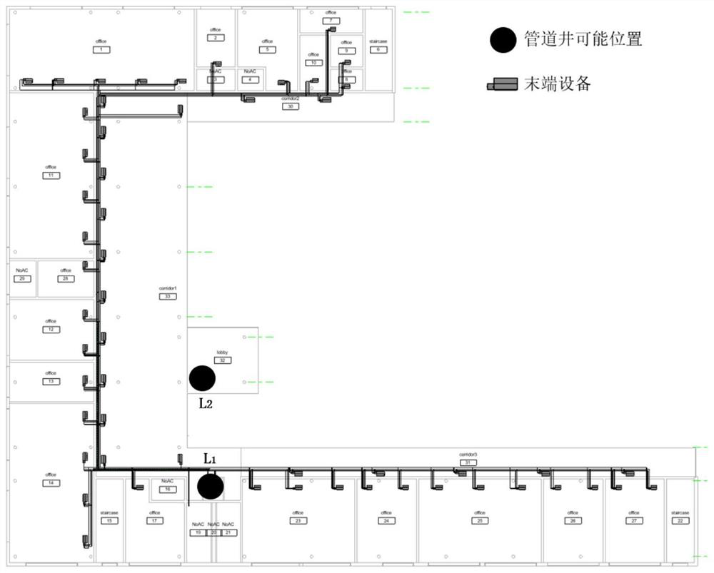
[0057] Step 1) Obtain the coordinate set L of the possible position coordinates of the pipeline well ktsj , each coordinate in the set will be used as the starting point u for solution in step 4) 0 . There are two possible positions of pipeline wells in this embodiment, which are image 3 with Figure 4 L in 1 , L 2 .

[0058] Step 2) Obtain the terminal equipment coordinate set T from the building information model or the design result. In this embodiment, the coordinates of the terminal equipment are obtained from the design r...


PUM


Abstract

The invention discloses a piping shaft optimization algorithm, and relates to the field of architectural design and electromechanical design. The method is characterized by comprising the following steps of: extracting room information and possible positions of the piping shafts from a building information model, and automatically solving a shortest path pipeline from each possible position of each piping shaft to each tail end by adopting a Pramer algorithm on the basis of a graph theory and a minimum spanning tree thought in combination with an arrangement position of tail end equipment in electromechanical design; and calculating the resistance of each solved shortest path pipeline and the unbalance degree of the system, and selecting the piping shaft with the minimum pipeline resistance within 15% of the unbalance degree of the system as the optimal piping shaft position. The comprehensive optimal design of simple system pipeline arrangement, good system balance, resistance reduction, energy-saving operation and the like is achieved.

Description

technical field [0001] The invention relates to the fields of architectural design and electromechanical design, in particular to an optimization algorithm for pipeline wells. Background technique [0002] The pipeline well in the building is often the starting point of the pipeline in the plan design of the mechanical and electrical system. The location of the pipeline well directly affects the layout of the pipeline system. A reasonable pipeline well location is very important for the design of the building's mechanical and electrical system. The position of the pipe well in the current actual project is often determined by construction professionals according to the needs of the construction profession, while the mechanical and electrical designers who actually use the pipe well only check whether the size of the pipe well meets the requirements, which will largely cause the location of the pipe well to be set. Unreasonable situation. Nowadays, the building information m...

Claims


Application Information

Patent Timeline
IPC IPC(8): G06F30/13G06F30/18G06F113/14
CPCG06F30/13G06F30/18G06F2113/14
Inventor 许鹏郭明月何睿凯陈志森陈喆陈永保
Owner TONGJI UNIV
Why Eureka
Try Eureka