
Protective agricultural insect killing equipment

A kind of equipment and agricultural technology, which is applied in the field of protective agricultural insecticide equipment, can solve the problems of complicated installation process, damage to crops and insect killer lamps, economic losses, etc., and achieve high safety performance, good insecticide effect, and strong lodging resistance Effect

Inactive Publication Date: 2021-01-19
朱明新
View PDF0 Cites 0 Cited by
  • Summary
  • Abstract
  • Description
  • Claims
  • Application Information

AI Technical Summary

Problems solved by technology

[0004] Since the insecticidal lamps work in the field for a long time, it is inevitable to resist some severe weather such as strong wind, explosion, heavy rain, etc. The existing general-purpose insecticidal equipment on the market often needs to be driven into concrete in the field for the installation of the insecticidal lamps. Pile, and then install the insecticidal lamp by bolts, because the effective insecticidal area of ​​each lamp is limited, this will cause multiple concrete piles to be driven into the field to install the insecticidal lamp, and the planting area will be lost. The installation process It is complicated, and it is difficult to remove the concrete piles in the later stage; the other is the in-line type, which sets the bottom into a sharp pointed shape and is directly inserted into the ground by manpower or machines, but this method is relatively unreliable and easy to be damaged in bad weather. Overturning, damage to crops and pest control lamps, causing economic losses, especially in soft soil like paddy fields

Method used


Image

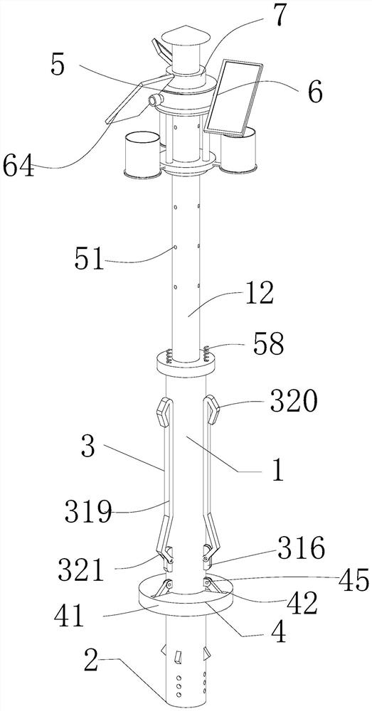
  • Protective agricultural insect killing equipment
  • Protective agricultural insect killing equipment
  • Protective agricultural insect killing equipment

Examples


Embodiment Construction

[0020] In order to enable those in the technical field to better understand the solutions of the present invention, the technical solutions in the embodiments of the present invention will be clearly and completely described below in conjunction with the drawings in the embodiments of the present invention.

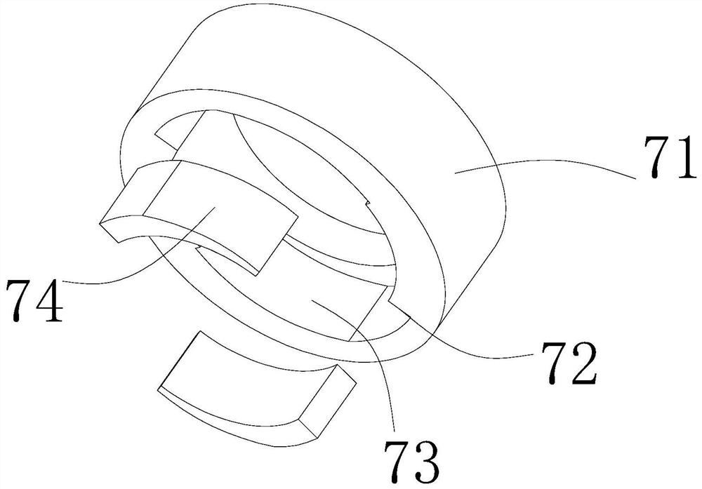
[0021] like Figure 1-7 As shown, a protective agricultural insecticide equipment includes a stainless steel support seat 1, a punch mechanism 2, an expansion mechanism 3, a pressure mechanism 4, a mounting hole 11, a column 12, a mounting table 13, an insect killing lamp 14, and a fixed rod 15. Protection mechanism 5, split photovoltaic panel 6, card sleeve mechanism 7; the punch mechanism 2 is set at the bottom of the stainless steel support seat 1; the expansion mechanism 3 is set at the bottom of the stainless steel support seat 1; the The pressing mechanism 4 is set in the middle of the expansion mechanism 3; the mounting hole 11 is set on the upper part of the stai...


PUM


Abstract

The invention discloses a protective agricultural insect killing device. The protective agricultural insect killing device comprises a stainless steel supporting base, a punch mechanism arranged on the stainless steel supporting base, an expansion mechanism arranged on the stainless steel supporting base, a covering and pressing mechanism arranged on the expansion mechanism, a mounting hole formedin the stainless steel supporting base, a stand column detachably mounted in the mounting hole, a mounting table slidably connected to the stand column, a disinsection lamp detachably connected to the mounting table, a fixing rod fixedly connected to the mounting table, a protection mechanism detachably connected to the fixing rod, a split type photovoltaic panel rotatably connected to the protection mechanism and a clamping sleeve mechanism slidably connected to the stand column. Safer and more reliable ground fixation suitable for various kinds of soil is achieved through the expansion mechanism; an active protection mechanism in severe weather is realized through the protection mechanism, the lodging resistance is higher, and the safety performance is higher; and the height of the deinsectization lamp can be freely adjusted through the clamping sleeve mechanism, and therefore the optimal deinsectization effect is achieved.

Description

technical field [0001] The invention belongs to the technical field of agricultural equipment, in particular to a protective agricultural insecticidal equipment. Background technique [0002] After the 1970s, China's planting industry began to use a large amount of chemical pesticides to prevent diseases and insect pests; some pesticides remained directly or indirectly in various agricultural products, livestock products, aquatic products, soil and water, resulting in pesticide residues. Agricultural products and foods with highly toxic pesticide residues can cause acute poisoning of humans and animals, such as poisonous leeks and poisonous cowpeas; eating agricultural and sideline products with excessive pesticide residues will not cause acute poisoning symptoms, but long-term consumption will cause chronic poisoning of humans and animals. Lead to the occurrence of diseases, and even affect the next generation; the quality and safety of China's agricultural products lags be...

Claims


Application Information

Patent Timeline
IPC IPC(8): A01M1/04
CPCA01M1/04
Inventor 朱明新
Owner 朱明新
Learn More