Calcining device for ceramic structural part

A technology for calcination devices and structural parts, which is applied in the direction of furnace components, electric furnace heating, furnace types, etc., which can solve the problems of low calcination efficiency and achieve the effect of avoiding slow temperature rise

Pending Publication Date: 2021-01-15
江苏恒祥宇新材料有限公司
View PDF0 Cites 0 Cited by
  • Summary
  • Abstract
  • Description
  • Claims
  • Application Information

AI Technical Summary

Problems solved by technology

[0003] When ceramics are manufactured, they often need to be calcined to make porcelain. Generally, the workpiece to be calcined is first placed in a calciner, and then heated and fired by laying heating devices around the calciner. However, in the existing calcination equipment, in order to improve the calcination efficiency during calcination, racks are generally installed in the calcination device, but the racks are generally fixed, and in order to improve the heating and calcination efficiency and uniform distribution, they are generally distributed in a single layer. , so the calcination efficiency is low

Method used


Image

  • Calcining device for ceramic structural part
  • Calcining device for ceramic structural part
  • Calcining device for ceramic structural part

Examples


Embodiment Construction

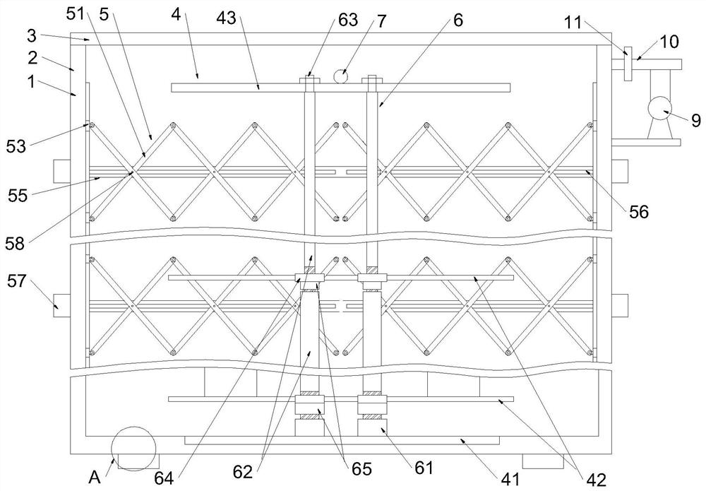
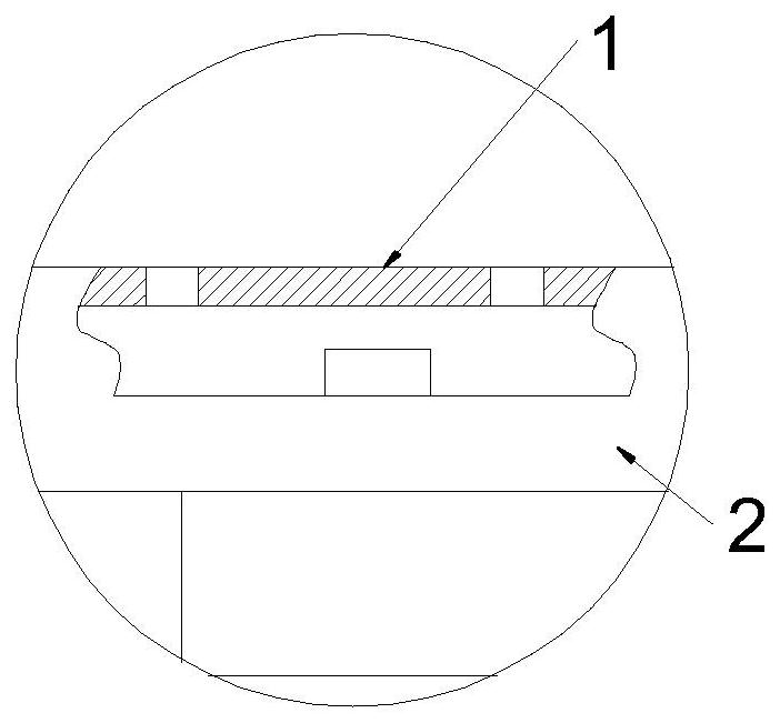
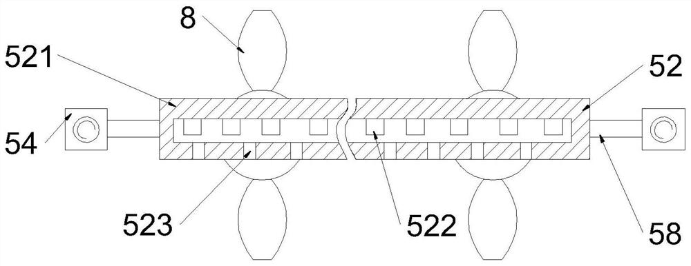
[0021] combine Figure 1 to Figure 4 The calcination device of a ceramic structural part shown in this embodiment includes a calcination furnace body 2 with a calcination layer 1 laid on the inner wall and a cover 3 sealed and closed on the top of the calcination furnace body 2, and also includes a shelf 4 and the level heating group 5, the shelf 4 includes positioning plates 41 distributed sequentially from bottom to top, at least two sets of shelf bodies 42 and hanging plate frames 43, the bottom of the calciner body 2 is provided with positioning plates 41 for positioning The positioning groove, and the positioning plate 41, the storage plate body 42 and the hanging plate frame 43 are fixedly connected by two sets of connecting column groups 6, and at least one group of lifting rings 7 is fixed on the top of the hanging plate frame 43; Between the two groups of storage board bodies 42 and between the storage board body 42 and the hanging plate frame 43, two sets of relative...


PUM


Abstract

The invention provides a calcining device for a ceramic structural part. The calcining device for the ceramic structural part comprises a calcining furnace body, a cover body, a storage plate frame and a hierarchical heating group, wherein the storage plate frame comprises a positioning plate, at least two groups of storage plate bodies and a hanger plate frame which are sequentially distributed from bottom to top; the hierarchical heating group comprises two groups of horizontal folding and stretching frames and heating units; each horizontal folding and stretching frame comprises a pluralityof folding rod piece sets connected side by side; first sliding blocks hinged to the ends of rod piece units are longitudinally connected to the side wall of the calcining furnace body in a sliding mode; second sliding blocks are fixed to one ends of pin shafts; transverse sliding grooves matched with the second sliding blocks are formed in the side wall of the calcining furnace body; screw rodspenetrating through the second sliding blocks are erected in the transverse sliding grooves; the end parts of the screw rods penetrate out of the calcining furnace body and are in driving connection with motors; and the second sliding blocks at the farthest end of the motors are in threaded connection with the screw rods. The calcining device for the ceramic structural part provided by the invention is simple in structure, the calcining efficiency and the heat distribution uniformity can be improved, and the taking and the placing are conducted in a more trouble-saving, faster and more convenient way.

Description

technical field [0001] The invention relates to a calcining device, in particular to a calcining device for ceramic structural parts. Background technique [0002] Ceramics is the general term for pottery and porcelain. It is generally made of clay as the main raw material and various natural minerals through crushing, mixing, molding and calcination, as well as various products. [0003] When ceramics are manufactured, they often need to be calcined to make porcelain. Generally, the workpiece to be calcined is first placed in a calciner, and then heated and fired by laying heating devices around the calciner. However, in the existing calcination equipment, in order to improve the calcination efficiency during calcination, racks are generally installed in the calcination device, but the racks are generally fixed, and in order to improve the heating and calcination efficiency and the uniform distribution is generally a single-layer distribution , so the calcination efficienc...

Claims


Application Information

Patent Timeline
IPC IPC(8): F27B17/00F27D5/00F27D11/02
CPCF27B17/0041F27B17/0075F27D5/00F27D11/02
Inventor 曹恒樑
Owner 江苏恒祥宇新材料有限公司
Why Eureka
Try Eureka