
Test cable control device

A control device and testing cable technology, which can be used in measurement, wellbore/well components, earthwork drilling and production, etc., and can solve the problems of high labor intensity for testers

Pending Publication Date: 2021-01-15
贵州航天凯山石油仪器有限公司
View PDF12 Cites 0 Cited by
  • Summary
  • Abstract
  • Description
  • Claims
  • Application Information

AI Technical Summary

Problems solved by technology

[0003] The purpose of the present invention is to provide a test cable control device to solve the current problems of high labor intensity of test personnel and risks of manual climbing operations

Method used


Image

  • Test cable control device
  • Test cable control device

Examples


Embodiment Construction

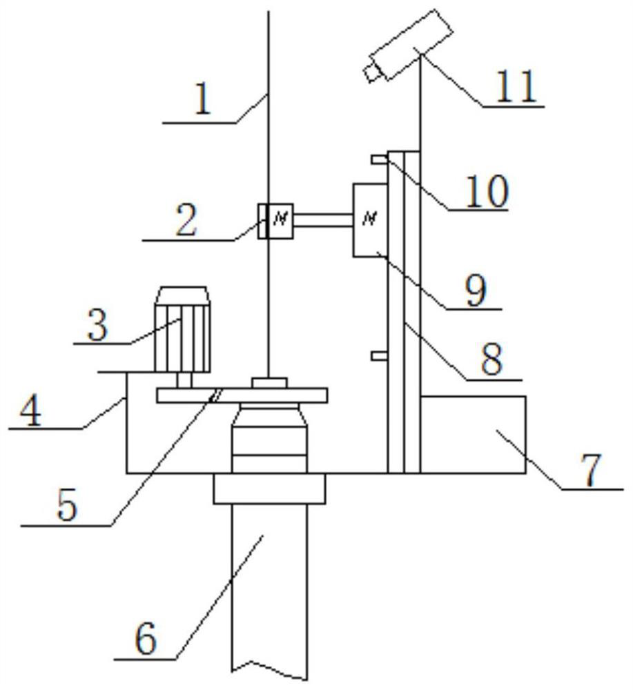
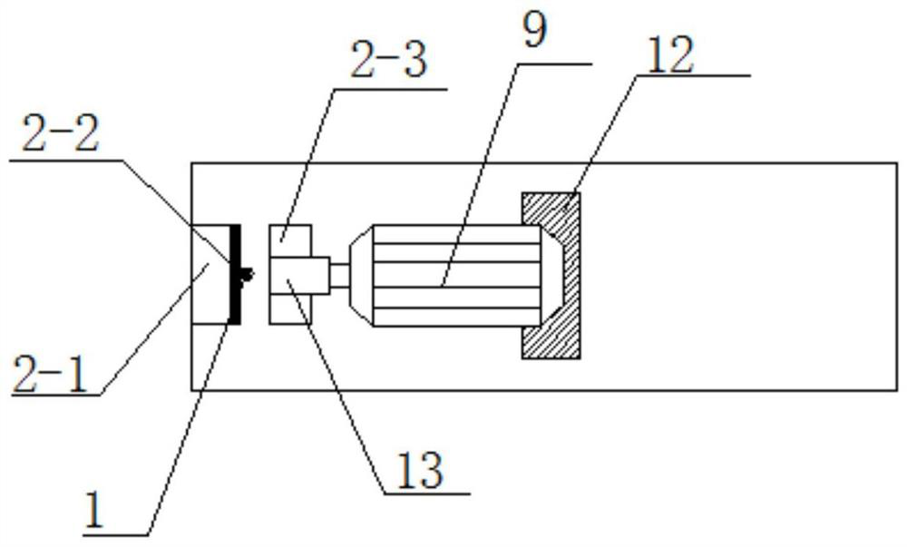
[0018] Such as Figure 1-2 As shown, a test cable control device includes a blowout preventer 6 installed on the base, and a pressure cap adjustment device is installed on the upper end of the blowout preventer 6 . The pressure cap adjustment device includes a pressure cap adjustment gear 5 connected to the blowout preventer 6, the pressure cap adjustment gear 5 is keyed to a second motor 3, and the second motor 3 is used to adjust and control precise torque, so The second motor 3 is installed on the base through an adjustable bracket 4 . The adjustable support 4 is a movable support, which ensures the ease of installation of the whole device.

[0019] A cable 1 is installed on the upper end of the pressure cap adjustment device, and a cable clamping device 2 is installed on the cable 1, and the cable clamping device 2 is located above the pressure cap adjustment device. The cable clamping device 2 includes a clamping block 2-1 installed on one side of the cable 1, and a cla...


PUM


Abstract

The invention discloses a test cable control device. The test cable control device comprises a blowout prevention pipe installed on a base, wherein a pressing cap adjusting device is installed at theupper end of the blowout prevention pipe, a cable is arranged at the upper end of the pressing cap adjusting device, a cable clamping device is arranged on the cable, and the cable clamping device islocated above the pressing cap adjusting device; the cable clamping device is connected with a first motor, and the first motor is arranged on an up-down moving device; and the pressing cap adjustingdevice, the first motor and the up-down moving device are all electrically connected with a control box. According to the test cable control device, the cable is automatically pushed, the pushing force and the clamping force can be controlled, and the cable is not damaged under the limit pushing force; and remote visual adjustment is achieved, operation is easy, automatic adjustment does not needconfiguration personnel, the action condition of each motor can be directly observed, and the safety and reliability are high.

Description

technical field [0001] The invention relates to the technical field of oilfield test cables, in particular to a test cable control device. Background technique [0002] After the oil field is exploited in the middle and later stages, the method of water injection or polymer flooding into the formation is generally used to ensure the crude oil production. The injection well layered measurement and adjustment technology has been promoted and implemented in oilfields for many years, and has played a significant role in improving the economic benefits of oilfields. Layer-by-layer measurement and adjustment mainly uses cables to lower direct-reading measurement and adjustment instruments into the well to measure and adjust each layer, and the cables are lowered into the well from the ground through the blowout pipe. During the test operation, it is necessary for the tester to stand on the operating table to disassemble the blowout prevention plug, and to adjust the pressure cap ...

Claims


Application Information

Patent Timeline
IPC IPC(8): E21B47/00E21B23/14
CPCE21B47/00E21B23/14
Inventor 罗玉林魏炎红
Owner 贵州航天凯山石油仪器有限公司
Learn More