
Minimum air strip calculation method considering image control points on two sides of railway

A calculation method and technology of image control points, applied in the field of UAV aerial survey, can solve the problems of neglecting safety and efficiency, and achieve the effect of improving field work efficiency, reducing the number of routes, and reducing the probability

Pending Publication Date: 2021-01-08
CHINA RAILWAY SHANGHAI DESIGN INST GRP
View PDF4 Cites 0 Cited by
  • Summary
  • Abstract
  • Description
  • Claims
  • Application Information

AI Technical Summary

Problems solved by technology

When laying out image control points and route planning, the main consideration is accuracy, but safety and efficiency are often ignored

Method used


Image

  • Minimum air strip calculation method considering image control points on two sides of railway
  • Minimum air strip calculation method considering image control points on two sides of railway
  • Minimum air strip calculation method considering image control points on two sides of railway

Examples


Embodiment Construction

[0023] The features of the present invention and other related features will be further described in detail below in conjunction with the accompanying drawings through embodiments, so as to facilitate the understanding of those skilled in the art:

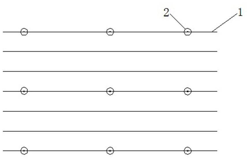
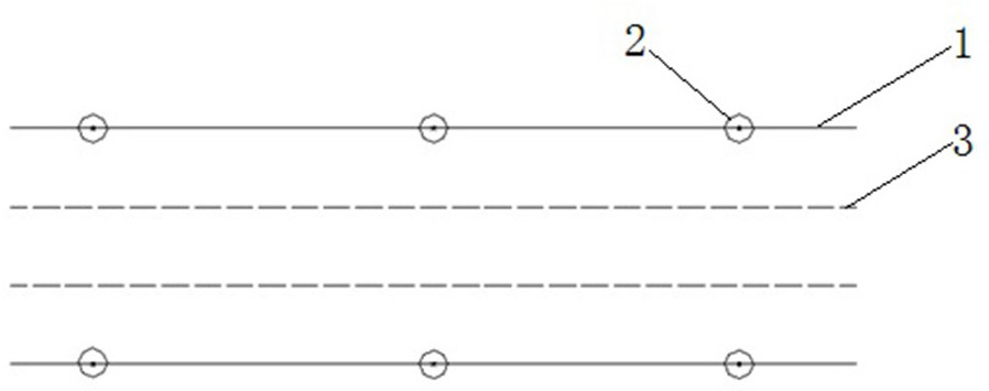
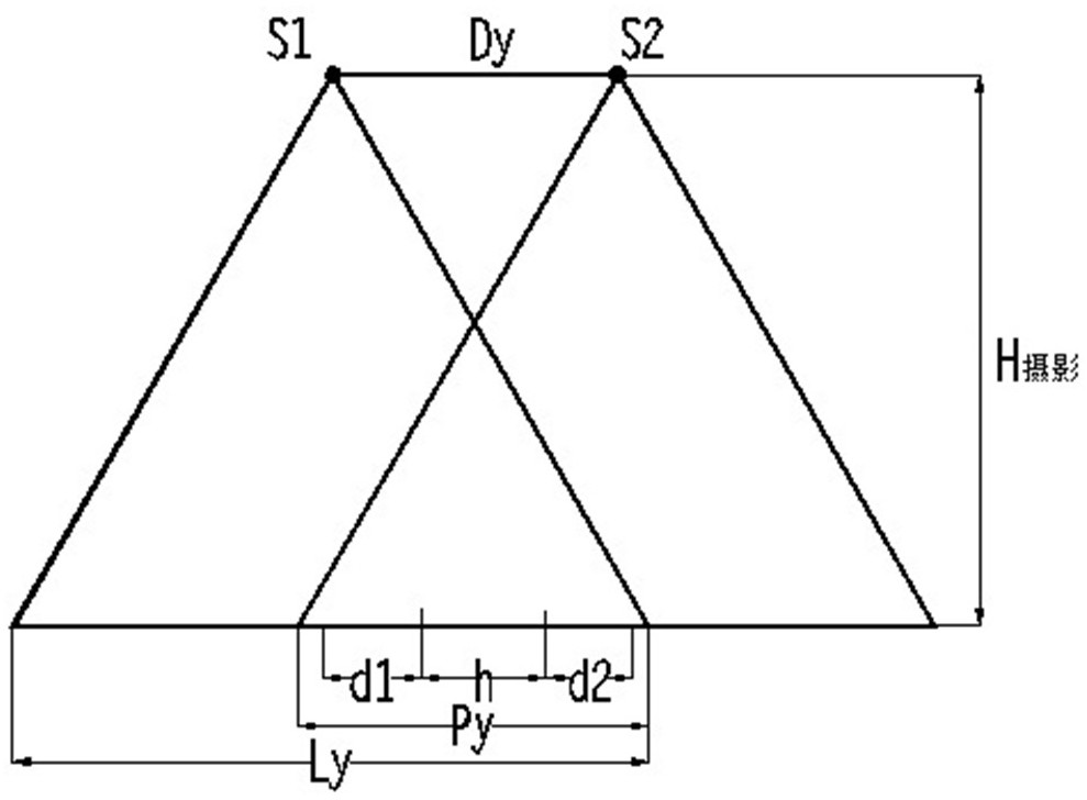
[0024] Such as Figure 1-3 As shown, each mark in the figure is respectively represented as: planning route 1, image control point 2, existing line protection range 3, image control point S1, and image control point S2.

[0025] Embodiment: the conventional arrangement of image control points in the prior art is to arrange the image control points by using the two ends of the route and the middle interval of one or two routes to arrange level height points, such as figure 1 As shown; therefore, it often requires aerial photography drones to fly one by one along multiple flight belts, and the flight mileage is long and time-consuming.

[0026] combine figure 2 and image 3 As shown, the method for calculating the least flight be...


PUM


Abstract

The invention belongs to the technical field of aerial survey of unmanned aerial vehicles and relates to a minimum air strip calculation method considering image control points on two sides of a railway. According to the method of the invention, a row of air strips is arranged along each of two sides of an existing line protection range of an existing railway; and an air strip position corresponding to the optimal flight height and the optimal lateral overlapping rate is determined on the basis of the range value of the lateral overlapping rate and the range value of the optimal flight height.The method has the advantages that: 1) the safety of an existing line is ensured, an air route is far away from the existing line protection range, and the probability that an unmanned aerial vehiclefalls into the existing line is greatly reduced; 2) the setting of the air route is purposeful, a strip-shaped air route can be planned in a targeted manner in advance with the width of the existingline protection range known; 3) the field work efficiency is improved, arranged field image control points are reduced on the premise of ensuring that precision meets requirements, and the number of air routes is reduced.

Description

technical field [0001] The invention relates to the technical field of unmanned aerial vehicle surveying, in particular to a method for calculating the least flight zone taking into account image control points on both sides of a railway. Background technique [0002] As drone technology matures, more and more industries are introducing drone technology. my country's railway construction is developing faster and faster, and the railway network is becoming more and more complex. It is very necessary to use drone aerial surveys on existing railways. [0003] The general process of the conventional existing railway aerial survey is to determine the photographic area—arrange the image control points—plan the route—execute the flight mission. When laying out image control points and route planning, the main consideration is accuracy, but safety and efficiency are often ignored. Railways, especially high-speed railways, have very high safety requirements. Once a drone fails, it ...

Claims


Application Information

Patent Timeline
Patent Type & Authority Applications(China)
IPC IPC(8): G01C11/00G01C11/08G01C21/20
CPCG01C11/00G01C11/08G01C21/20
Inventor 孙喜烨王文庆范先铮帅明明
Owner CHINA RAILWAY SHANGHAI DESIGN INST GRP
Learn More