New energy drying device

A drying device and new energy technology, applied in drying, dryers, heating devices, etc., can solve the problems of disassembly and replacement of unfavorable heating pipes, less power energy, and single collection channels, so as to improve drying efficiency and product quality quality, increase power energy, and enhance the effect of safety performance

Pending Publication Date: 2021-01-08
贾雨凝
View PDF5 Cites 0 Cited by
  • Summary
  • Abstract
  • Description
  • Claims
  • Application Information

AI Technical Summary

Problems solved by technology

[0006] The purpose of the present invention is to provide a new energy drying device to solve the above-mentioned background technology when collecting and generating new energy, the collection channel is single, and the power energy generated is less, so the work of the drying device is generated. It is inconvenient, and when the heating tube works for a long time, it lacks heat dissipation inside the tank of the device, which hinders the safety of the drying work, and the position of the heating tube is fixed, which is not conducive to the disassembly and replacement of the heating tube in the later stage. When the product is drying, the position of the product pallet is fixed, which makes the product easy to accumulate, which affects the drying effect of the product, the drying efficiency is low, and the device cannot reprocess the product, and the product drying effect is not good The problem

Method used


Image

  • New energy drying device
  • New energy drying device
  • New energy drying device

Examples


Embodiment Construction

[0030] The following will clearly and completely describe the technical solutions in the embodiments of the present invention with reference to the accompanying drawings in the embodiments of the present invention. Obviously, the described embodiments are only some, not all, embodiments of the present invention. Based on the embodiments of the present invention, all other embodiments obtained by persons of ordinary skill in the art without making creative efforts belong to the protection scope of the present invention.

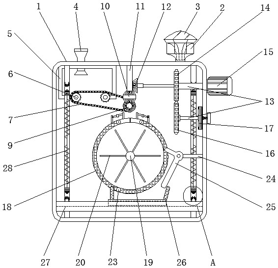
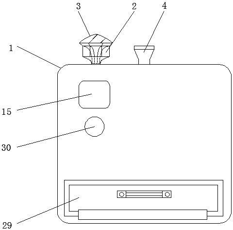
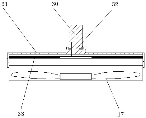
[0031] see Figure 1-8 , the present invention provides a technical solution: a new energy drying device, including a tank body 1 and a reclaiming door 29, an air inlet 2 is provided at the right end of the top surface of the tank body 1, and a solar panel 3 is installed on the top of the air inlet 2, The left end of the top surface of the tank body 1 is provided with a feed inlet 4, and the lower end of the feed inlet 4 runs through the top surface of the fix...


PUM


Abstract

The invention discloses a new energy drying device. The new energy drying device comprises a tank body and a material taking door, an air inlet is formed in the right end of the top face of the tank body, a solar panel is installed at the top of the air inlet, a feeding port is formed in the left end of the top face of the tank body, the lower end of the feeding port penetrates through the top face of a fixing frame, and the fixing frame is installed at the left end of the top inside the tank body; and rolling shafts are installed on the two sides of the bottom of the fixing frame, the outer sides of the rolling shafts are attached to the inner side of one end of a conveying belt, the inner side of the other end of the conveying belt is connected with a first fixing shaft, and meanwhile, one end of the first fixing shaft is installed at the upper middle position of the rear side inside the tank body. According to the new energy drying device, when a product is dried, a screen drum anda stirring rod synchronously rotate, the product is conveniently scattered and dried, a shifting rod can shift a supporting plate, the product can be uniformly spread on the supporting plate when falling off from the screen drum, the product is conveniently dried again, and the drying efficiency and the product quality are improved.

Description

technical field [0001] The invention relates to the field of new energy technology, in particular to a new energy drying device. Background technique [0002] New energy, also known as unconventional energy, refers to various forms of energy other than traditional energy, generally renewable energy that is developed and utilized on the basis of new technologies, such as solar energy, geothermal energy, wind energy, ocean energy, biomass energy and Nuclear fusion energy, etc., when using new energy for drying work, can reduce the use of non-renewable energy and protect national petrochemical resources. However, the existing drying devices generally have the following problems when they are used; [0003] 1. When collecting new energy for power generation, the collection channel is single and the power energy generated is less, which will cause inconvenience to the work of the drying device, and when the heating tube works for a long time, there is no need to check the inside ...

Claims


Application Information

Patent Timeline
IPC IPC(8): F26B11/04F26B23/04F26B25/16B07B1/22F03D9/25H02S10/00
CPCB07B1/22F26B11/04F26B23/04F26B25/16F03D9/25H02S10/00Y02E10/50Y02E10/72Y02P70/10
Inventor 贾雨凝高延帅
Owner 贾雨凝
Why Eureka
Try Eureka