
A low-pressure turbine air-cooled blade

A low-pressure turbine and blade technology, applied in the field of aero-engine blades, can solve the problems of blocking the trailing edge cold air channel inlet, large cold air flow angle, large inlet cold air pressure loss, etc. The effect of smooth flow of cold air

Active Publication Date: 2022-06-07
AECC SHENYANG ENGINE RES INST
View PDF8 Cites 0 Cited by
  • Summary
  • Abstract
  • Description
  • Claims
  • Application Information

AI Technical Summary

Problems solved by technology

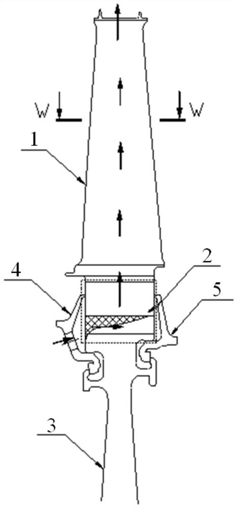
[0002] In the prior art, the air-cooled blades of the low-pressure turbine have a relatively large flow angle after the cold air enters from the cooling hole of the front baffle, and at the same time, the flow of the cold air impinges on the rear baffle and stagnates, resulting in a large pressure loss of the imported cold air, and the cold air is in the rear. After the position of the baffle is stagnant, it will block the inlet of the cold air channel at the trailing edge, which will lead to the deterioration of the flow of the cold air channel at the trailing edge of the blade, the temperature of the trailing edge will increase, and the damage to the blade will be greater, which cannot meet the use requirements of the air-cooled blade of the low-pressure turbine

Method used


Image

  • A low-pressure turbine air-cooled blade
  • A low-pressure turbine air-cooled blade
  • A low-pressure turbine air-cooled blade

Examples


Embodiment Construction

[0031] In order to make the purpose of the implementation of the present application, the technical solution and advantages of the implementation of the present application more clear, the following will be combined with the drawings in the embodiment of the present application, the technical solution in the embodiment of the present application is described in more detail. In the drawings, the same or similar designations from beginning to end represent the same or similar elements or elements with the same or similar functions. The embodiments described are a portion of the embodiments of the present application, but not all embodiments. The embodiments described below by reference to the accompanying drawings are exemplary and are intended to be used to explain the present application, and cannot be construed as a limitation of the present application. Based on the embodiments in the present application, all other embodiments obtained by those of ordinary skill in the art witho...


PUM


Abstract

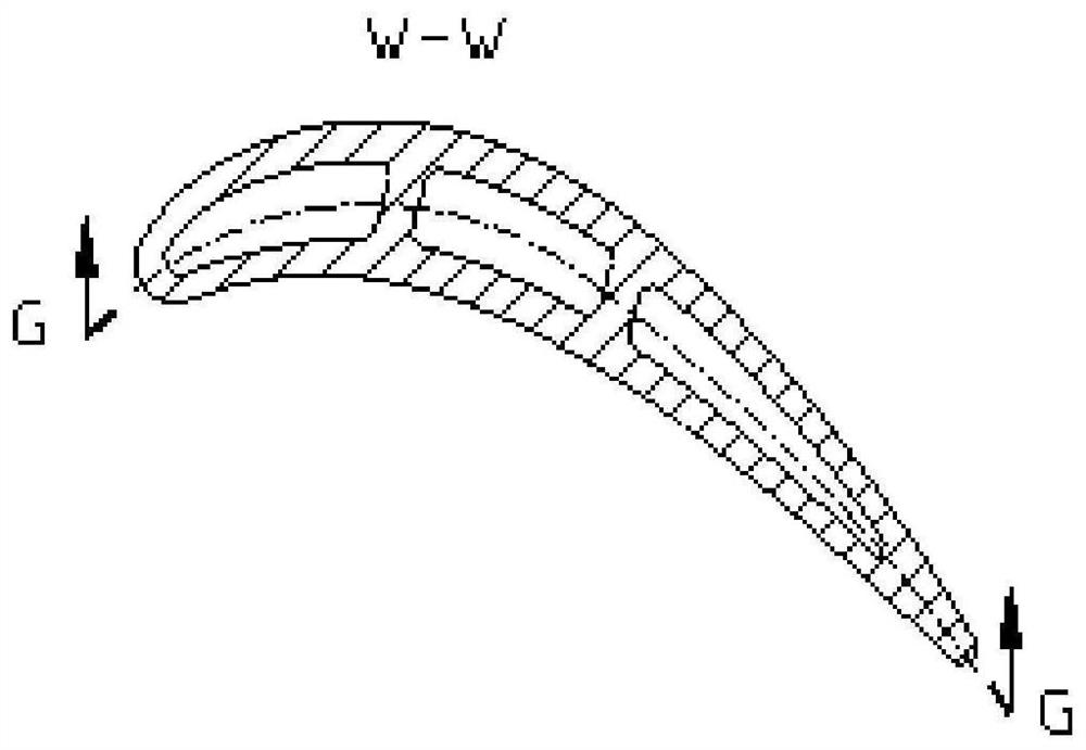
The application belongs to the field of aeroengine blades, in particular to a low-pressure turbine air-cooled blade. Including: blade (1), disk tenon (2), turbine disk (3), front baffle (4) and rear baffle (5). The low-pressure turbine air-cooled blade of this application is connected to the tenon (2) of the low-pressure turbine disk through a fir tree-shaped tenon, the blade (1) is axially positioned through the front and rear baffles, and the blade (1) is a crowned hollow air-cooled blade , the cold air enters from the cold air inlet of the front baffle (4), passes through the cold air channel between the tenons, and enters the cold air channel of the blade (1) from the three cold air ports on the lower surface of the tenon of the blade (1), and the blade (1) has three cold air channels The cavity straight channel cooling structure, the cold air flows out from the cold air outlet of the blade crown after heat exchange with the inner wall surface, and finally discharged into the main channel. The air-cooled blade of the low-pressure turbine of the present application has a smoother flow of the cold air inlet of the tenon structure, significantly reduces the flow resistance loss, effectively alleviates the airflow blockage of the cold air inlet of the trailing edge channel, and can effectively reduce the temperature level of the trailing edge.

Description

Technical field [0001] The present application belongs to the field of aero engine blades, specifically involving a low-pressure turbine air-cooled blade. Background [0002] In the prior art, the low-pressure turbine air-cooled blade due to the cold air from the front baffle cooling hole after the entry of the cold air, the cold air flow angle is larger, while the cold air impact to the tailgate flow stagnation, the comprehensive result of the import air pressure loss is larger, the cold air in the tailgate position is delayed, blocking the tail edge air-conditioning channel inlet, resulting in the tail edge of the cold air channel flow deterioration, the tail edge temperature increases, the damage to the blade is larger, can not meet the use requirements of the low-pressure turbine gas-cooled blade. [0003] Therefore, it is desirable that there is a technical solution to overcome or at least mitigate at least one of the above defects of the prior art. Contents of the Inventio...

Claims


Application Information

Patent Timeline
Patent Type & Authority Patents(China)
IPC IPC(8): F01D5/18F01D5/30
CPCF01D5/187F01D5/30F01D5/3015Y02T50/60
Inventor 杨珂马世岩袁昌于荣斌
Owner AECC SHENYANG ENGINE RES INST
Learn More