A protective sleeve for pipe fittings
A technology for protective sleeves and pipe fittings, applied in packaging, cleaning methods and appliances, chemical instruments and methods, etc., can solve the problems of insufficient protection of the main part of pipe fittings, and achieve the effect of convenient turnover transportation and convenient assembly
- Summary
- Abstract
- Description
- Claims
- Application Information
AI Technical Summary
Problems solved by technology
Method used
Image

Examples
Embodiment 1
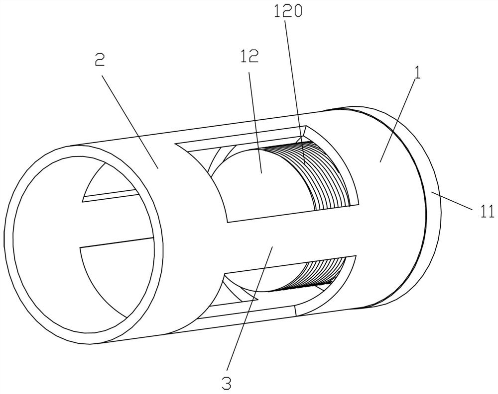
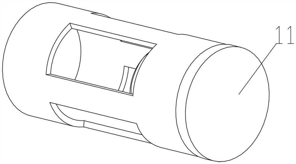
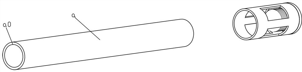
[0031] Example 1, such as Figure 1-6 As shown, a pipe fitting protection sleeve includes a port enclosure protection plate 1 for being sleeved on the outer wall of the port a0 of the pipe a, and is spaced from the port enclosure protection plate 1 in the axial direction of the port enclosure protection plate 1 Distributed and used to cover the main body enclosure protection plate 2 on the outer wall of the pipe a The port enclosing ring protection plate 1 is an axially extending reinforcement connecting rib plate 3. The port enclosing ring protection plate 1 is to be sleeved on the port a0 of the pipe fitting a, and is placed on the outer wall. It should be noted that the port enclosing ring protection plate 1 is in the axial direction. It should exceed a part of the port a0 of the pipe fitting a, so that the port a0 of the pipe fitting a can be better protected so that the port a0 of the pipe fitting a will not be exposed. The main body enclosing ring protection plate 2 is ...
Embodiment 2
[0040] Example 2, such as Figure 7 As shown, a pipe fitting structure includes a pipe fitting protection sleeve for protecting the pipe fitting a and installed at the end of the pipe fitting a. The pipe fitting protection sleeve is connected with a connecting rod b, and the other end of the connecting rod b is connected to a Universal joint device b1, said universal joint device b1 is installed and connected on a support plate b2, and the bottom of said support plate b2 is installed and connected with universal roller b3. This kind of pipe fitting structure is mainly for the convenience of being installed at both ends of the pipe fitting, so that the pipe fitting can be moved in all directions more easily, and is convenient for transportation. The structure of the pipe fitting protective sleeve involved has a better use effect, so that the protective sleeve can not only protect the pipe fitting but also be conveniently used for the turnover pipe fitting. On the position, thr...
Embodiment 3
[0045] Example 3, such as Figure 8 As shown, a pipe fitting assembly includes the pipe fitting structure described in Embodiment 2 and the pipe fitting a. Both the front and rear ends of the pipe a are provided with the pipe structure. The two ends of the pipe fitting only need to be sleeved on the pipe fitting protective sleeve on the pipe fitting structure.
PUM
 Abstract
Description
Claims
Application Information
 - R&D
- Intellectual Property
- Life Sciences
- Materials
- Tech Scout
- Unparalleled Data Quality
- Higher Quality Content
- 60% Fewer Hallucinations
Browse by: Latest US Patents, China's latest patents, Technical Efficacy Thesaurus, Application Domain, Technology Topic, Popular Technical Reports.
© 2025 PatSnap. All rights reserved.Legal|Privacy policy|Modern Slavery Act Transparency Statement|Sitemap|About US| Contact US: help@patsnap.com