
A kind of demulsification separation device for vaccine processing

A separation device and demulsification technology, which is applied in the field of vaccine cultivation, can solve the problems of inability to emulsify vaccines, low demulsification efficiency, inability to demulsify vaccines, etc., and achieve the effect of improving demulsification efficiency and stirring effect

Active Publication Date: 2022-06-17
中普生物制药有限公司
View PDF11 Cites 0 Cited by
  • Summary
  • Abstract
  • Description
  • Claims
  • Application Information

AI Technical Summary

Problems solved by technology

[0004] The above-mentioned patent also has the following disadvantages: only through the demulsification hole to demulsify the vaccine, the vaccine cannot be demulsified well, and the position of the stirring rod in the above-mentioned device is fixed, and the demulsification holes are all arranged on the stirring rod. On the pole, the vaccine cannot be fully emulsified, resulting in low demulsification efficiency of the device

Method used


Image

  • A kind of demulsification separation device for vaccine processing
  • A kind of demulsification separation device for vaccine processing
  • A kind of demulsification separation device for vaccine processing

Examples


Embodiment 1

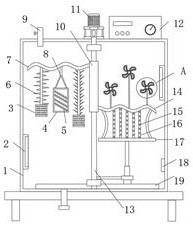
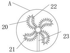
[0030] refer to Figure 1-4 , a demulsification and separation device for vaccine processing, comprising a demulsification and separation box 1, the top outer wall of the demulsification and separation box 1 is fixed with a motor 11 by screws, and the output shaft of the motor 11 is connected with a rotating rod 13 through a coupling. The bottom inner wall of the milk separation box 1 is fixed with a slide rail 19 by screws, and the inner wall of the slide rail 19 is slidably connected with a hydraulic rod 24 through a slider. The top outer wall of the hydraulic rod 24 is fixed with a cross bar 17 by screws, and the Both sides of the top outer wall are welded with arc rods 26, the outer wall of the rotating rod 13 is slidably connected with a sliding sleeve 10, and the top and bottom of both sides of the outer wall of the sliding sleeve 10 are respectively welded with a first wave rod 7 and a second wave rod 14. , both sides of the bottom outer wall of the second wave rod 14 a...

Embodiment 2

[0038] refer to Figure 5 , a demulsification and separation device for vaccine processing. Compared with Embodiment 1, this embodiment also includes a pressure gauge 29 fixed to the outer wall of the top of the demulsification and separation box 1 by screws. A pressure relief pipe 30 is connected, and an outer wall of one side of the pressure relief pipe 30 is connected with a pressure relief valve through a thread.

[0039] Connect the equipment to the power supply, add the vaccine and demulsifier into the demulsification separation box 1 through the feeding pipe 9, turn on the motor 11, the motor 11 drives the rotating rod 13 to rotate, and then the fixed rod drives the hydraulic rod 24 inside the slide rail 19 Rotate, connect the hydraulic rod 24 to the hydraulic system, and adjust the length of the hydraulic rod 24 to make the sliding sleeve 10 slide up and down on the outer wall of the rotating rod 13, and then the first wave rod 7 and the second wave rod 14 are rotated....


PUM


Abstract

The invention belongs to the technical field of vaccine cultivation, in particular to a demulsification separation device for vaccine processing. Aiming at the problem of poor demulsification efficiency, the following scheme is proposed, comprising a demulsification separation box, the top outer wall of the demulsification separation box is equipped with motor, and the output shaft of the motor is connected with a rotating rod through a coupling, the bottom inner wall of the demulsification separation box is provided with a slide rail, and the inner wall of the slide rail is slidably connected with a hydraulic rod, and the top outer wall of the hydraulic rod is provided with crossbar. The present invention is equipped with a slide rail, a hydraulic rod, a sliding sleeve, a first wave rod, a second wave rod, a second stirring rod, a demulsification needle, a stirring plate, and a second demulsification hole, and the demulsification needles have different angles and lengths With different structures, the second demulsification hole is also a structure with different sizes and specifications, which can demulsify vaccines located in different positions. The second demulsification hole and demulsification needle can break the emulsified oil particles in the vaccine solution, It can comprehensively improve the stirring effect of the stirring mechanism and improve the efficiency of demulsification.

Description

technical field [0001] The invention relates to the technical field of vaccine cultivation, in particular to a demulsification separation device for vaccine processing. Background technique [0002] The vaccine needs to be demulsification during the production process, and then the oil phase and the water phase are separated to achieve the effect of purifying the vaccine. The prior art adopts the addition of a demulsifier, and the demulsification is carried out by stirring. The demulsification efficiency is low and the vaccine production speed is reduced, which is urgently needed. A device for demulsification and separation of vaccines is developed to solve the above problems. [0003] After searching, the Chinese patent authorization number is CN210170889U, which discloses a device for vaccine demulsification and separation, including a support plate, a universal wheel, a handle, a discharge port, a tank, a refrigeration mechanism, a temperature sensor, and a stirring devic...

Claims


Application Information

Patent Timeline
Patent Type & Authority Patents(China)
IPC IPC(8): B01D17/04
CPCB01D17/047B01D17/041
Inventor 程联
Owner 中普生物制药有限公司
Learn More