Etching equipment for printed circuit board
A technology for printed circuit boards and etching equipment, which is applied in the field of etching equipment for printed circuit boards, and can solve problems such as inability to clean the circuit board etching solution.
- Summary
- Abstract
- Description
- Claims
- Application Information
AI Technical Summary
Problems solved by technology
Method used
Image
Examples
Embodiment 1
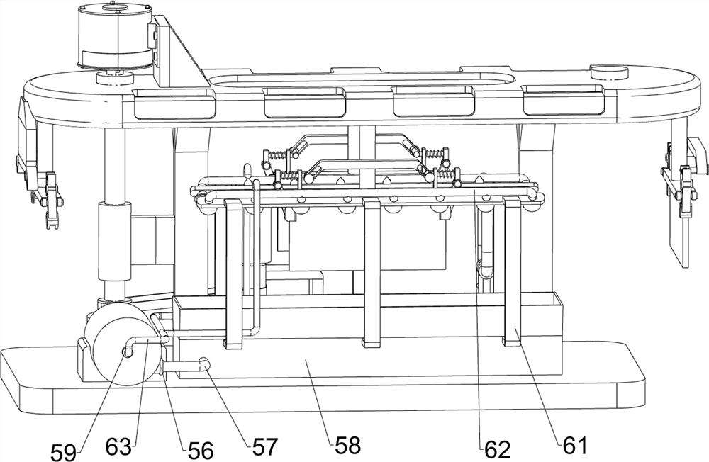
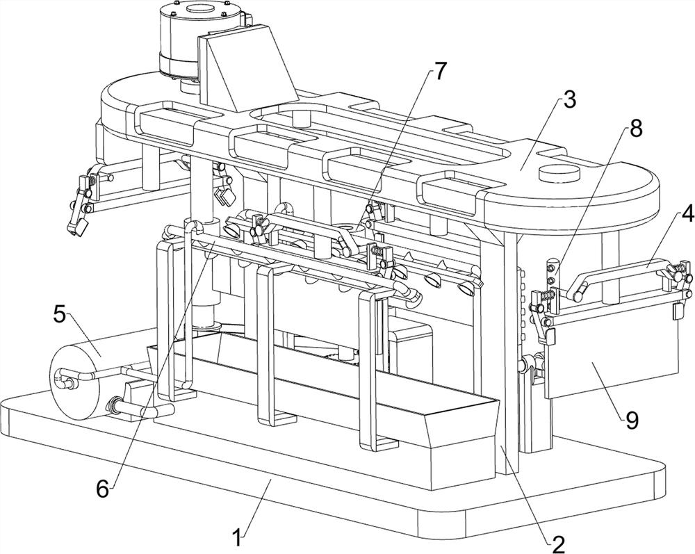
[0026] An etching device for printed circuit boards, such as Figure 1-4 As shown, it includes a bottom plate 1, a support frame 2, a moving mechanism 3, a material clamping mechanism 4, a pressurizing mechanism 5, and a liquid spraying structure 6. A support frame 2 is connected in the middle of the top of the bottom plate 1, and a moving mechanism 3 is provided on the support frame 2. , The moving mechanism 3 is provided with a clamping mechanism 4, the top of the bottom plate 1 is provided with a pressurizing mechanism 5, and the pressurizing mechanism 5 is provided with a liquid spraying structure 6.
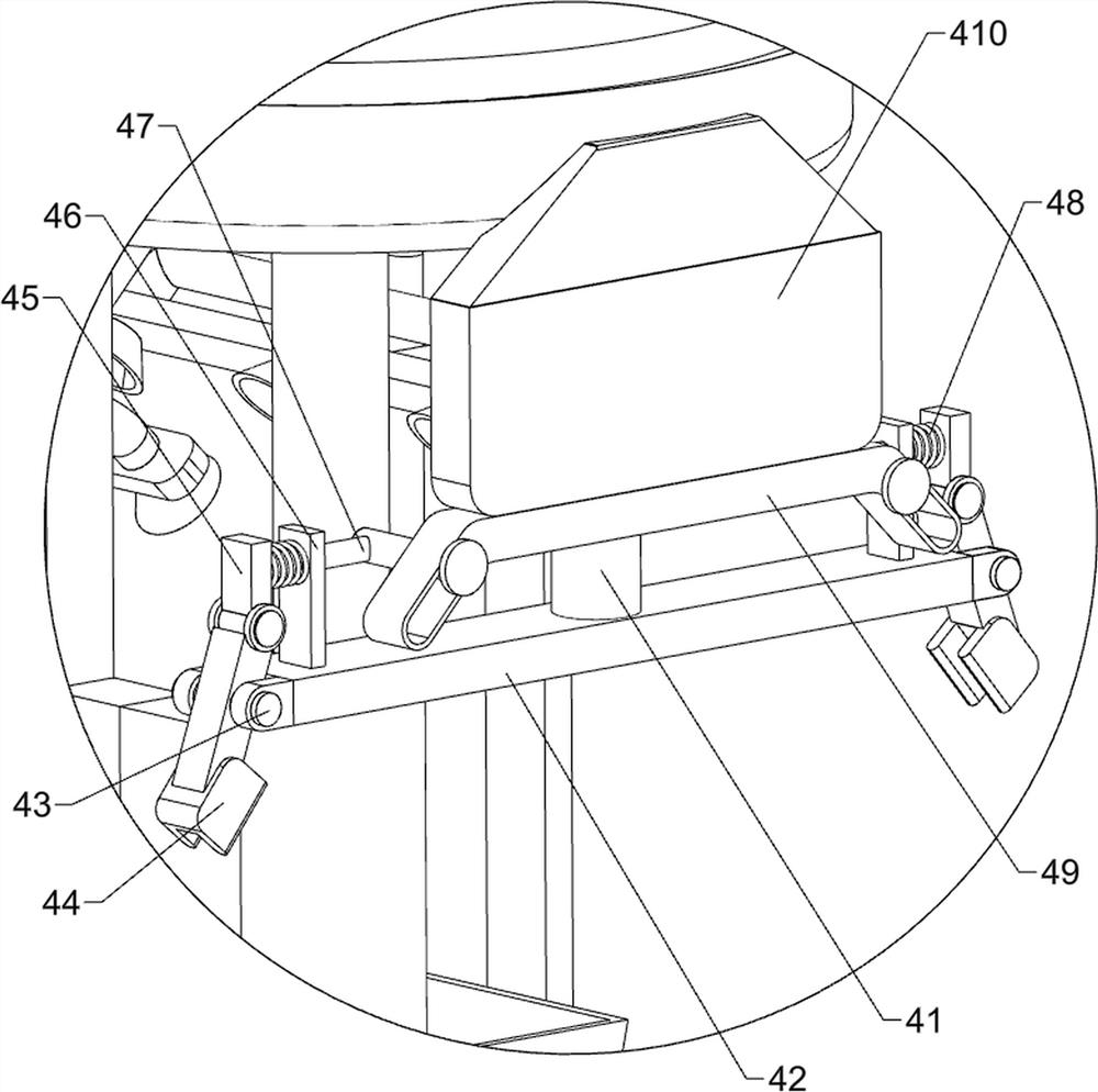
[0027] The moving mechanism 3 includes a limited housing 31, a mounting block 32, a servo motor 33, a pulley shaft 34 and a flat belt 35, the top of the support frame 2 is connected with a limited housing 31, and the left side of the limiting housing 31 is connected with a mounting block 32, and the mounting block 32 The left side is equipped with a servo motor 33, and the l...
Embodiment 2
[0033] On the basis of Example 1, such as figure 2 As shown, also includes erasing mechanism 7, and erasing mechanism 7 comprises sponge cylinder 71, second fixed frame 72, gear 73 and transmission belt group 74, and bottom plate 1 top left rear side is connected with second fixed frame 72, the second On the two fixed frames 72, there are two sponge rollers 71 symmetrically connected to each other in front and back rotation, the bottom of the sponge roller 71 is connected with a gear 73, and the two gears 73 are meshed, and a drive belt set is connected between the drive shaft 55 and the rear sponge roller 71. 74.
[0034] Drive shaft 55 rotates and rotates the sponge cylinder 71 on the rear side through the transmission belt set 74, and the two sponge cylinders 71 can be rotated oppositely by the gear 73, and the circuit board 9 after the etching can be completed by the two sponge cylinders 71. Clean up, wipe off the etchant on the circuit board 9 after etching.
Embodiment 3
[0036] On the basis of Example 2, such as figure 2 As shown, a flushing structure 8 is also included. The flushing structure 8 includes a third fixed frame 81, a water spray pipe 82 and a water pipe joint 83. The right rear side of the top of the bottom plate 1 is connected with a third fixed frame 81. A water spray pipe 82 is connected, and a water pipe joint 83 is connected to the water spray pipe 82 .
[0037] The water pipe joint 83 can be connected to the external water pipe, and the clear water enters the water spray pipe 82 through the water pipe joint 83, and the water spray pipe 82 sprays the clear water subsequently, so that the etched circuit board 9 can be rinsed, so that the circuit board 9 can be flushed. The plate 9 is rinsed clean to prevent the sponge roller 71 from directly contacting the etching solution, thereby preventing the sponge roller 71 from being corroded.
PUM
 Abstract
Description
Claims
Application Information
 - R&D
- Intellectual Property
- Life Sciences
- Materials
- Tech Scout
- Unparalleled Data Quality
- Higher Quality Content
- 60% Fewer Hallucinations
Browse by: Latest US Patents, China's latest patents, Technical Efficacy Thesaurus, Application Domain, Technology Topic, Popular Technical Reports.
© 2025 PatSnap. All rights reserved.Legal|Privacy policy|Modern Slavery Act Transparency Statement|Sitemap|About US| Contact US: help@patsnap.com


