Tool for aligning and assembling balance shaft
A technology of balance shaft and tooling, which is applied in the direction of spring/shock absorber, vibration suppression adjustment, mechanical equipment, etc., to achieve the effect of saving operating hours, firm clamping and low cost
- Summary
- Abstract
- Description
- Claims
- Application Information
AI Technical Summary
Problems solved by technology
Method used
Image
Examples
specific Embodiment approach 1
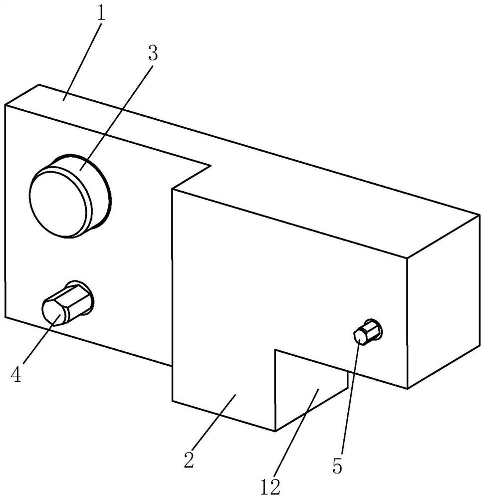
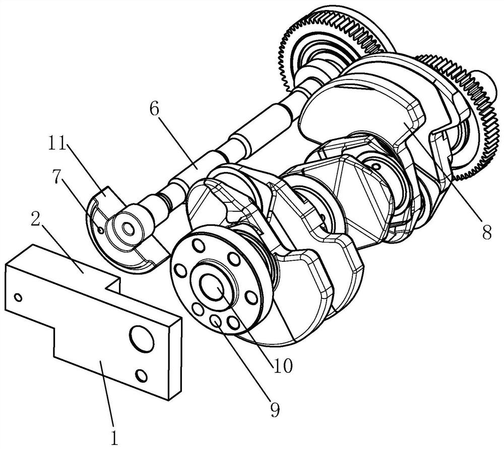
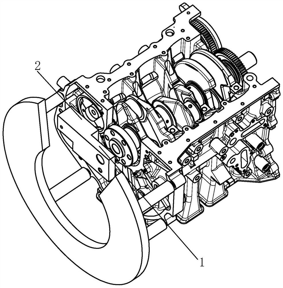
[0015] Specific implementation mode one: as Figure 1 ~ Figure 3 As shown, the present invention discloses a tooling for aligning and assembling a balance shaft, including a base block 1, a leveling bump 2, a crankshaft center pin 3, a crankshaft side pin 4 and a balance shaft pin 5, and the base block 1 is installed One end facing the balance shaft 6 is provided with a leveling bump 2, the leveling bump 2 is integrally cast with the base block 1, and the integrally cast base block 1 and the leveling bump 2 cooperate with the end surface of the crankshaft 8 and the balance shaft 6. For the height difference generated by the end faces, when in use, the installation end face of the leveling bump 2 is matched with the rear end face of the balance shaft quality block 11 of the balance shaft 6, and the installation end face of the base block 1 is matched with the rear end face of the rear flange of the crankshaft 8; The outer end of the leveling bump 2 is provided with a gap 12 tha...
specific Embodiment approach 2
[0016] Embodiment 2: This embodiment is a further description of Embodiment 1. The mounting surface of the leveling bump 2 is provided with a balance shaft pin installation hole, and the balance shaft pin 5 is embedded in the balance shaft with an interference fit. In the shaft pin installation hole; the installation surface of the base block 1 is provided with a crankshaft center pin installation hole and a crankshaft side pin installation hole, and the crankshaft center pin 3 is embedded in the crankshaft center pin installation hole with an interference fit. The crankshaft side pin 4 is interference fitted and embedded in the crankshaft side pin installation hole.
specific Embodiment approach 3
[0017] Specific implementation mode three: as figure 1 As shown, this embodiment is a further description of specific embodiment 1 or 2. The outer ends of the crankshaft center pin 3 , crankshaft side pin 4 and balance pin 5 are all provided with chamfers to avoid damage to the parts.
PUM
 Abstract
Description
Claims
Application Information
 - R&D Engineer
- R&D Manager
- IP Professional
- Industry Leading Data Capabilities
- Powerful AI technology
- Patent DNA Extraction
Browse by: Latest US Patents, China's latest patents, Technical Efficacy Thesaurus, Application Domain, Technology Topic, Popular Technical Reports.
© 2024 PatSnap. All rights reserved.Legal|Privacy policy|Modern Slavery Act Transparency Statement|Sitemap|About US| Contact US: help@patsnap.com


