
Atomizing cup with adjustable collision distance

An atomization cup and distance technology, which is applied in the field of medical nebulizers, can solve problems such as the inability to achieve accurate adjustment of fogging volume and droplet diameter, the inability to ensure the same lifting and lowering of the collision surface, and the inability to accurately control the rotation adjustment angle. Achieve the effects of good fogging effect, small adjustment error, and avoid adjustment error

Pending Publication Date: 2021-01-05
JIANGSU YUYUE MEDICAL EQUIP&SUPPLY CO LTD +4
View PDF1 Cites 1 Cited by
  • Summary
  • Abstract
  • Description
  • Claims
  • Application Information

AI Technical Summary

Problems solved by technology

[0006] In the existing atomization cup technical solutions, such as the patent "Atomization tank with adjustable atomization particle size" with the application number CN201720848477.4, an atomization tank capable of adjusting the collision distance (that is, the atomization In this patent, the atomizing cup uses a threaded structure to adjust the distance between the collision surface and the jet hole up and down in a rotating manner, thereby adjusting the size of the droplets; but this structure cannot achieve the amount of fog and the droplet Accurate adjustment of the diameter, in the process of moving the collision surface up and down through the screw drive, firstly, the rotation adjustment angle cannot be accurately controlled, and secondly, even if a certain rotation angle is controlled, because the material of the atomization cup is generally plastic, its transmission The accuracy is low, and the same rotation angle can not guarantee the same amount of lifting and lowering of the collision surface each time, and the error is large

Method used


Image

  • Atomizing cup with adjustable collision distance
  • Atomizing cup with adjustable collision distance
  • Atomizing cup with adjustable collision distance

Examples


Embodiment 1

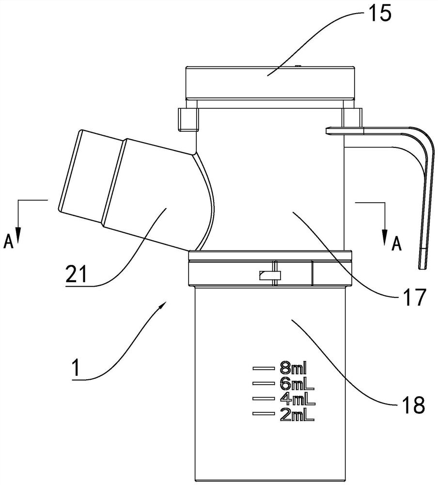
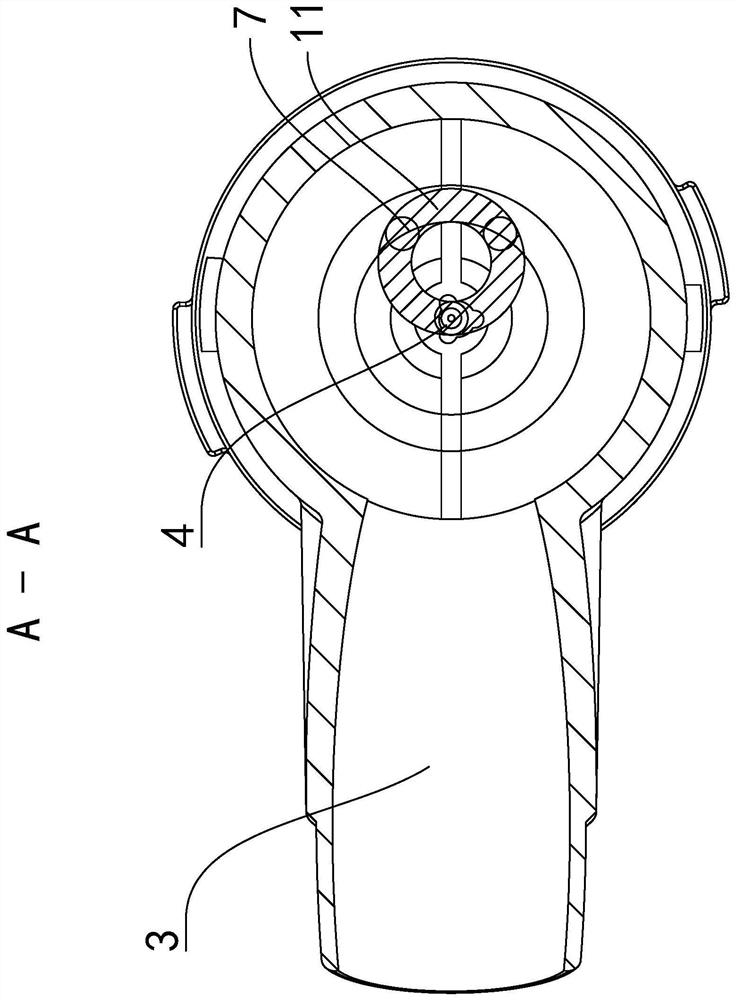
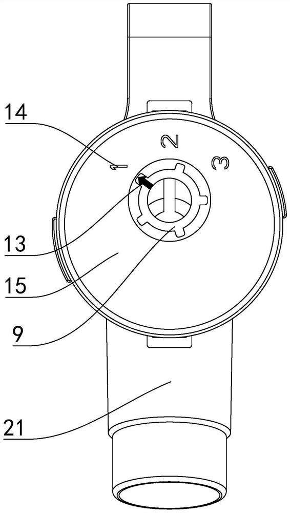
[0069] Embodiment one: see attached figure 1 to attach Figure 5 As shown, an atomization cup with adjustable collision distance includes a cup shell 1, a cup cover 15, a cup core 16, a mist outlet 21 and a venturi tube 20;

[0070] There is a cavity 2 in the cup shell 1, and the part containing the liquid medicine in the cavity 2 is defined as the lower part;

[0071] The cup shell 1 is composed of an upper cup 17 and a lower cup 18, the lower end of the upper cup 17 is embedded in the upper opening of the lower cup 18; the venturi tube 20 is positioned at the bottom end of the lower cup 18, and the venturi tube 20 The jet port 4 is located in the cavity 2; the cup core 16 is covered on the upper end of the Venturi tube 20 in a clearance fit manner, the gap between the two is a drainage gap 22, and the cup core 16 is provided with a hole for the jet to pass through. In the assembled state, the hole is aligned up and down with the jet port 4, and the lower end of the upper c...

Embodiment 2

[0082]Embodiment two: see attached Figure 6 , the difference between embodiment two and embodiment one is:

[0083] The adjustment part 5 is a slider 12, and the slider 12 is slidably arranged in the interlayer 19 on the upper end of the cup shell 1 vertically. The lower end surface of the block 12 is fixedly connected to the upper end of each of the collision bodies 6;

[0084] Each of the colliding bodies 6 is extended along the vertical direction, and is fixedly connected to the slider 12 in a parallel arrangement, and the arrangement direction is the same as the sliding direction of the slider 12;

[0085] In the sliding state, the motion trajectory of each collision surface 7 forms a straight strip, and viewed from the up and down direction, the jet port 4 is located on the motion trajectory of each collision surface 7, so that the jet port 4 can face each collision surface with different collision distances 7;

[0086] Preferably, the collision assembly further inclu...

Embodiment 3

[0088] Embodiment three: see attached Figure 7 , the difference between embodiment three and embodiment one is:

[0089] The adjustment part 5 is rotationally connected with the cup shell 1, and the rotation axis 10 of the turntable 8 forms an obtuse angle with the jet direction 3 of the jet port 4;

[0090] Each of the collision bodies 6 is a bent cylinder, and the arrangement of the collision surface 7 of each collision body 6 around the rotating shaft 10 is fixedly connected with the adjustment part 5, and the axial distance of each collision surface 7 from the rotating shaft 10 is equal;

[0091] In the rotating state, the trajectory of each collision surface 7 forms a circular ring, and its circular trajectory is not perpendicular to the jet flow direction 3, and viewed along the jet flow direction 3, the jet port 4 is located on the trajectory of each collision surface 7, and each collision surface 7 The collision distances with the jet ports 4 are not equal, so that t...


PUM


Abstract

The invention discloses an atomizing cup with the adjustable collision distance. The cup comprises a cup shell and a collision assembly, wherein a jet flow opening is formed in a containing cavity ofthe cup shell; the collision assembly is of an integrated structure formed by fixedly connecting an adjusting part and a plurality of collision bodies in an up-down manner; and the adjusting part is positioned in the cup shell in a rotating or sliding mode. An operator rotates or moves the adjusting part, and the collision surfaces on the collision bodies below the adjusting part are driven to rotate around the jet flow direction or move in the direction perpendicular to the jet flow direction, so that different collision surfaces are switched to directly face the jet flow opening, and the purpose of adjusting the collision distance is achieved.

Description

technical field [0001] The invention relates to the field of medical nebulizers, in particular to a jet-type atomizing cup used in nebulization inhalation therapy. Background technique [0002] Nebulization inhalation therapy is a treatment method for respiratory diseases such as asthma, bronchitis and pharyngitis, among which jet nebulization cup is the mainstream equipment for nebulization inhalation treatment. [0003] The main function of the atomization cup is to atomize the liquid medicine in the cup for inhalation by the patient. The atomization process uses the Venturi principle to send external compressed air (or oxygen) into the atomization cup through the pipeline, and then from the mist A jet hole with a narrow cross-section inside the chemical cup ejects at high speed and hits the collision surface. The high-speed airflow generates a negative pressure area during the impact, so that the liquid medicine is sucked into the high-speed airflow under the action of th...

Claims


Application Information

Patent Timeline
Patent Type & Authority Applications(China)
IPC IPC(8): A61M15/00A61M11/00
CPCA61M15/0086A61M11/001A61M15/0001
Inventor 余先臣张佳王凯马骏赵帅
Owner JIANGSU YUYUE MEDICAL EQUIP&SUPPLY CO LTD
Learn More