
Pull-back-type safe self-destruction injection device

An injection device and a pull-back technology, which are applied in the field of pull-back safety self-destruction injection devices, can solve the problems of inability to fully realize zero-position injection, inability to inject gas or liquid, and threats to the personal safety of the injector, and achieve automatic destruction. , the effect of easy operation, improving the safety and convenience of use

Pending Publication Date: 2021-01-05
黄旭阳
View PDF0 Cites 0 Cited by
  • Summary
  • Abstract
  • Description
  • Claims
  • Application Information

AI Technical Summary

Problems solved by technology

At present, the existing syringes on the market have a series of problems due to structural design defects, among which there are two main problems that need to be solved urgently: 1. The zero injection cannot be fully realized, that is, the extracted gas or liquid cannot be fully injected. Second, after the injection is completed, in order to prevent the reuse of the syringe, it is usually necessary for the medical staff to separate the injection needle from the injection cylinder in a timely manner. However, once the management is not perfect Or illegal profit, these separated syringes may still be assembled and reused by criminals many times, and the personal safety of the injectees is greatly threatened

Method used


Image

  • Pull-back-type safe self-destruction injection device
  • Pull-back-type safe self-destruction injection device
  • Pull-back-type safe self-destruction injection device

Examples


Embodiment Construction

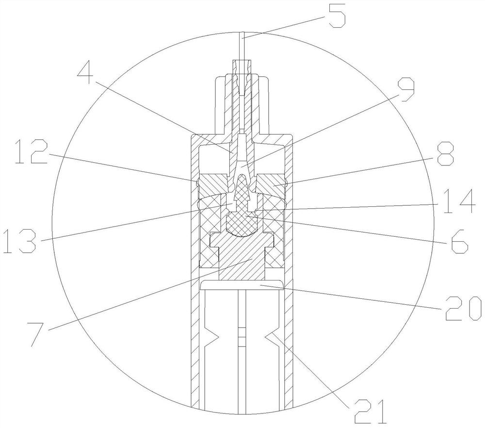
[0027] In order to make the technical problems, technical solutions and beneficial effects solved by the present invention clearer, the present invention will be further described in detail below in conjunction with the accompanying drawings and embodiments. It should be understood that the specific embodiments described here are only used to explain the present invention, not to limit the present invention.

[0028] In this application, the shape of the bottom end surface of the self-destruct rubber plug 8 is the same as that of the top end surface of the piston 3, so as to ensure zero-position injection when it is pushed to contact. In the through hole 10, the buckle fixing seat 10 is fixed by setting an annular protrusion in the middle and embedded in the groove in the through hole 10, so that the core rod 2 can push the piston 3 to move up and down during the moving process.

[0029] See Figure 1-9 Shown is a pull-back safety self-destruct injection device, including an ...


PUM


Abstract

The invention relates to a pull-back-type safe self-destruction injection device. The injection device comprises an outer cylinder, a core rod, a piston, a needle base and an injection needle, whereinthe core rod is movably inserted into the outer cylinder, the end of the core rod is located in the outer cylinder to fix the piston, the injection needle is inserted at the end of the outer cylinder, and the rear end of the injection needle is fixed through the needle base after the lower end of the injection needle is inserted in the outer cylinder. The self-destruction injection device is characterized in that a self-destruction assembly is further arranged in the outer cylinder; the self-destruction assembly comprises a core rod self-destruction buckle, a buckle fixing base, a self-destruction rubber plug and a buckle hole; a through hole is formed in the middle of the piston, and the buckle fixing base is embedded into the through hole; the core rod self-destruction buckle is embedded into the upper end of the buckle fixing base; the self-destruction rubber plug is embedded and fixed at the upper part of the inner wall of the outer cylinder; a conical through hole is formed in the middle of the self-destruction rubber plug, and the lower end of the needle base is embedded into the conical through hole to be fixed; and the buckle hole is formed in the lower end of the needle base in the length direction. According to the pull-back-type safe self-destruction injection device, zero-position injection can be achieved, automatic destruction of the injection device can be achieved, secondary utilization is avoided, and the use safety and convenience are improved.

Description

technical field [0001] The invention relates to the technical field of injection devices, in particular to a retractable safety self-destruction injection device. Background technique [0002] The injection device is more common with the syringe. A syringe is a common medical device, which is mainly used to extract or inject gas or liquid with an injection needle. At present, the existing syringes on the market have a series of problems due to structural design defects, among which there are two main problems that need to be solved urgently: 1. The zero injection cannot be fully realized, that is, the extracted gas or liquid cannot be fully injected. Second, after the injection is completed, in order to prevent the reuse of the syringe, it is usually necessary for the medical staff to separate the injection needle from the injection cylinder in a timely manner. However, once the management is not perfect Or illegal profit, etc., these separated syringes may still be assemb...

Claims


Application Information

Patent Timeline
Patent Type & Authority Applications(China)
IPC IPC(8): A61M5/178A61M5/31A61M5/315A61M5/50
CPCA61M5/178A61M5/31A61M5/31511A61M5/5066A61M2005/5073
Inventor 黄旭阳
Owner 黄旭阳
Learn More