
A mite remover

A technology for removing mites and mites, which is applied to vacuum cleaners, devices for capturing or killing insects, suction filters, etc., can solve the problems of poor air connection, cumbersome disassembly and assembly steps, missing parts and assembly steps, etc. It is not easy to assemble wrong steps, the disassembly process is simple and quick, and the effect of improving the efficiency of cleaning and maintenance

Active Publication Date: 2022-03-25
苏州睿克斯科技有限公司
View PDF11 Cites 0 Cited by
  • Summary
  • Abstract
  • Description
  • Claims
  • Application Information

AI Technical Summary

Problems solved by technology

[0003] Every once in a while, when the dust in the dust-gas separation device is full, the dust-gas separation device needs to be removed for cleaning. The installation method of the existing dust-gas separation device is cumbersome, and the unlocking and locking structure is complicated. During the installation and cleaning process, it is very easy to have problems such as low cleaning efficiency due to cumbersome steps, and poor connection of the air circuit after reassembly, which greatly reduces the user experience; in addition, after a period of use, the roller brush often Winding filaments such as hair, cotton wool, etc. Although the existing roller brush assembly adopts a detachable type to clean the filaments wound on the roller brush, most of the disassembly and assembly steps are cumbersome, and the user is in the cleaning process. It is very easy to have assembly errors caused by missing parts or wrong assembly steps, and after repeated disassembly and assembly, it is also very easy to have problems such as abnormal noise caused by unstable / loose installation of the roller brush, or even machine downtime and damage.

Method used


Image

  • A mite remover
  • A mite remover
  • A mite remover

Examples


Embodiment Construction

[0071] The technical solutions in the embodiments of the present invention will be clearly and completely described below in conjunction with the accompanying drawings in the embodiments of the present invention. Obviously, the described embodiments are only part of the embodiments of the present invention, not all of them. Based on the implementation methods in the present invention, all other embodiments obtained by persons of ordinary skill in the art without making creative efforts belong to the protection scope of the present invention.

[0072] In the drawings, the shapes and dimensions may be exaggerated for clarity, and the same reference numerals will be used throughout to designate the same or like parts.

[0073] Unless otherwise defined, the technical terms or scientific terms used herein shall have the usual meanings understood by those skilled in the art to which the present invention belongs. "First", "second" and similar words used in the patent application spe...


PUM


Abstract

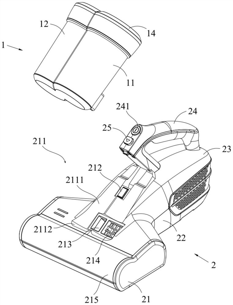
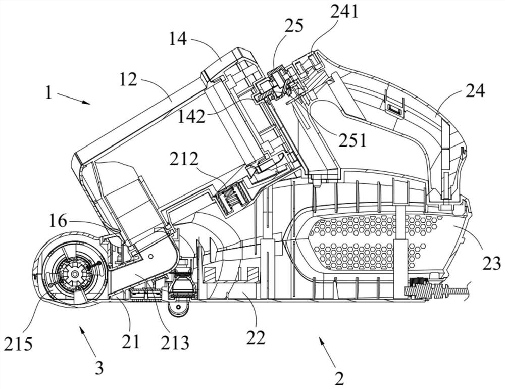
The invention discloses a mite removal instrument, comprising: a dust suction head part, the lower surface of which is parallel to the plane to be cleaned, and the lower surface of the dust suction head part is provided with a rolling brush chamber, a rolling brush The power chamber and the disinfection chamber; the suction generating chamber, which extends horizontally to the rear of the suction head part; the docking chamber, which connects the suction head part and the suction generating chamber; and the dust and gas separation device , which is detachably embedded above the dust suction head part and extends above the docking cavity; wherein, the dust and gas separation device is formed with an air inlet and an air exhaust port; the rear wall of the rolling brush chamber is provided with a suction Dust air duct, the dust suction air duct extends obliquely upwards in the dust suction head part and finally connects with the air inlet of the dust-gas separation device; The duct leads to the suction generating chamber. According to the present invention, it can improve the cleaning efficiency and user experience.

Description

technical field [0001] The invention relates to the field of vacuum cleaners, in particular to a mite removing instrument. Background technique [0002] In the field of vacuum cleaners, it is well known that mite removal instruments with different structures are used to remove dust and clean while removing mite and bacteria. In the process of researching and realizing dust removal, cleaning and mite removal and sterilization, the inventor found that the mite remover in the prior art has at least the following problems: [0003] Every once in a while, when the dust in the dust-gas separation device is full, the dust-gas separation device needs to be removed for cleaning. The installation method of the existing dust-gas separation device is cumbersome, and the unlocking and locking structure is complicated. During the installation and cleaning process, it is very easy to have problems such as low cleaning efficiency due to cumbersome steps, and poor connection of the air circ...

Claims


Application Information

Patent Timeline
Patent Type & Authority Patents(China)
IPC IPC(8): A47L7/00A47L9/04A47L9/32A47L9/16A01M17/00
CPCA47L7/0061A47L9/0411A47L9/322A47L9/1608A47L9/1683A47L9/1666A01M17/00
Inventor 潘家育
Owner 苏州睿克斯科技有限公司
Learn More