
Transmission signal processing method, device and system and storage medium

A technology for transmitting signals and processing methods, which is applied in the parts of TV systems, image communication, TV and other directions, which can solve the problem that the strobe light cannot feedback information, the bayonet system and the strobe light information exchange, and increase the hardware complexity and cost. and other issues, to achieve the effect of enriching the way of interaction and information transmission, comprehensive communication and feedback

Active Publication Date: 2020-12-29
ZHEJIANG UNIVIEW TECH CO LTD
View PDF6 Cites 2 Cited by
  • Summary
  • Abstract
  • Description
  • Claims
  • Application Information

AI Technical Summary

Problems solved by technology

[0003] However, in the current bayonet system and the application of the strobe light, there is no good information exchange between the bayonet system and the strobe light. The bayonet system can only issue a trigger command to the strobe light to trigger the strobe light to flash. , but other communication processes cannot be carried out, and the flashing light cannot feed back its own information to the bayonet
In addition, to communicate according to the current communication protocol, it is necessary to add hardware devices such as specific communication signal lines between the bayonet system and the flashing light, which increases the complexity and cost of the hardware, and cannot realize all bayonet systems and flashing lights. The transmission line settings between flashes are unified

Method used


Image

  • Transmission signal processing method, device and system and storage medium
  • Transmission signal processing method, device and system and storage medium
  • Transmission signal processing method, device and system and storage medium

Examples


Embodiment 1

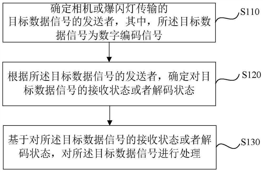
[0029] figure 1 It is a flowchart of a transmission signal processing method in Embodiment 1 of the present invention. The transmission signal processing method provided in this embodiment is applicable to the situation of processing the bidirectional transmission signal between the camera and the flashlight. The method can specifically be executed by a signal processing device, which can be implemented by software and / or hardware, and which can be integrated in a controller, which can be connected to a camera and / or a flashing light, and the camera can For a camera, it can also be a video camera, see figure 1 , the method of the embodiment of the present invention specifically includes:

[0030] S110. Determine the sender of the target data signal transmitted by the camera or the flashlight, wherein the target data signal is a digitally coded signal.

[0031] Wherein, the target data signal is a signal sent from the camera to the flashing light, or a signal sent from the f...

Embodiment 2

[0047] Figure 4 It is a flowchart of a transmission signal processing method in Embodiment 2 of the present invention. This embodiment is optimized on the basis of the above embodiments, details not described in detail in this embodiment can be found in the above embodiments. see Figure 4 , the transmission signal processing method provided in this embodiment may include:

[0048] S210. Determine that there is currently a target data signal for transmission, where the target data signal is a digital coded signal.

[0049] S220. If the controller is located in the camera, determine whether the current flag is the first flag, if yes, execute S250, if not, execute S230-S240.

[0050] Wherein, the first flag bit is a flag bit of the controller when the camera sends the target data signal.

[0051] Specifically, the first flag bit can be set by a technician according to actual conditions, for example, set to "0" or "1". The controller presets the flag bit and the correspondi...

Embodiment 3

[0062] Figure 5 It is a flowchart of a transmission signal processing method in Embodiment 2 of the present invention. This embodiment is optimized on the basis of the above embodiments, details not described in detail in this embodiment can be found in the above embodiments. see Figure 5 , the transmission signal processing method provided in this embodiment may include:

[0063] S310. Determine that there is currently a target data signal for transmission, where the target data signal is a digital coded signal.

[0064] S320. If the controller is located in the flashing light, judge whether the current flag is the second flag, if yes, execute S350, if not, execute S330-S340.

[0065] Wherein, the second flag bit is the flag bit of the controller when the flashing light sends the target data signal.

[0066] Specifically, the second flag bit can be set by a technician according to the actual situation, for example, set to "0" or "1". The controller pre-sets the flag bi...


PUM


Abstract

The embodiment of the invention discloses a transmission signal processing method, device and system and a storage medium. The method is executed by a controller and comprises the steps of: determining a sender of a target data signal transmitted by a camera or a flashing light, wherein the target data signal is a digital coded signal; determining a receiving state or a decoding state of the target data signal according to the sender of the target data signal; and processing the target data signal based on the receiving state or the decoding state of the target data signal. According to the invention, the receiving state or the decoding state of the target data signal is determined by judging the sender of the target data signal, so that the target data signal is processed in a targeted manner according to different senders, and the transmitted target data signal is selectively received or analyzed; and therefore, two-way communication between the camera and the flashing light is realized under the condition that a signal transmission line does not need to be added.

Description

technical field [0001] Embodiments of the present invention relate to the technical field of bayonet monitoring, and in particular to a transmission signal processing method, device, system and storage medium. Background technique [0002] The road vehicle intelligent detection and recording system (referred to as the bayonet) can realize the automatic collection and processing of road vehicle information, which involves the detection of the target object by the smart camera and the supplementary light process. During this process, the smart camera detects the situation of passing vehicles, and sends a trigger pulse (usually a switch value or a level value) to the flashing light through the trigger signal line, thereby triggering the flashing light to flash and realize ambient supplementary light. [0003] However, in the current bayonet system and the application of the strobe light, there is no good information exchange between the bayonet system and the strobe light, and...

Claims


Application Information

Patent Timeline
Patent Type & Authority Applications(China)
IPC IPC(8): H04N5/232H04N5/235
CPCH04N23/60H04N23/74
Inventor 徐凌峰陈迁钻陆益
Owner ZHEJIANG UNIVIEW TECH CO LTD
Learn More