A microwave field type wireless charging control method
A wireless charging and microwave field-type technology, which is applied in the direction of current collectors, electric vehicles, electrical components, etc., can solve the problems of low charging efficiency, low charging efficiency, and dependence on cables, etc., and achieve the effect of improving charging efficiency and saving energy
- Summary
- Abstract
- Description
- Claims
- Application Information
AI Technical Summary
Problems solved by technology
Method used
Image
Examples
Embodiment 1
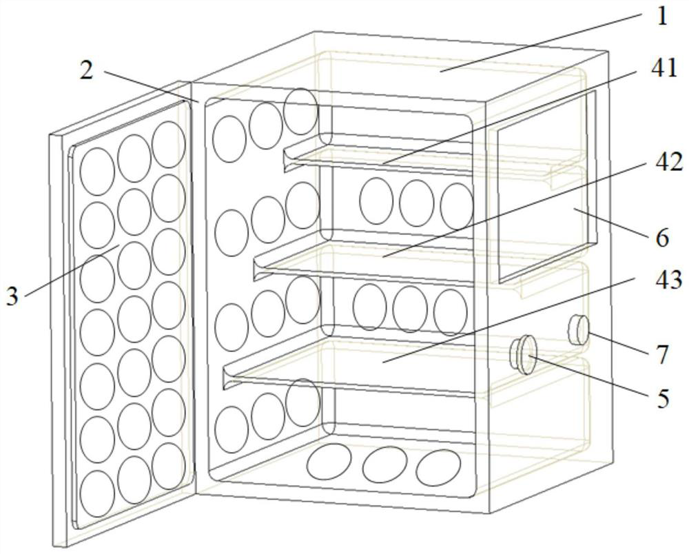
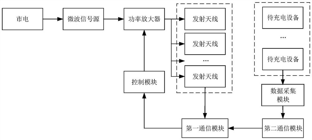
[0084] see figure 1 , figure 1 It is a schematic structural diagram of a microwave field type wireless charging device provided by an embodiment of the present invention. like figure 1 As shown, the device includes a casing 1, a cavity 2, a microwave signal source ( figure 1 not shown), power amplifier ( figure 1 not shown in), the transmitting antenna 3, the partition plate and the switch button 5 placed on the surface of the casing 1, the position acquisition module ( figure 1 not shown in) and the control module ( figure 1 not shown), wherein,
[0085] The cavity 2 has a box-type structure and is placed inside the casing 1 . When the cabinet door of the cavity 2 is closed, the casing 1 is used to shield the magnetic field in the cavity 2 . Wherein, the casing may be made of metal. The interior of the cavity is designed without edges and corners, that is, the circumference of the cavity and the contact points of the partition are rounded.
[0086] The separator is ar...
Embodiment 2
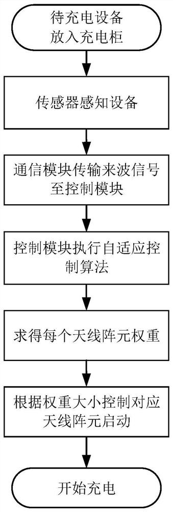
[0123] see Figure 8 , Figure 8 It is a schematic flowchart of a microwave field type wireless charging control method provided by an embodiment of the present invention. The method is applied to the charging process of the above-mentioned microwave field type wireless charging device, and can be executed by a control module in the microwave field type wireless charging device. like Figure 8 As shown, the charging control method provided by this embodiment specifically includes:
[0124] 110. Receive the position data of each device to be charged, and control the activation of the transmitting antenna at the corresponding position according to the position data.
[0125] Wherein, the transmitting antenna includes a plurality of antenna array elements arranged in an array form; the position data of the device to be charged can be obtained by a position sensor.
[0126] 120. Determine the weight of each antenna element in the activated transmit antenna.
[0127] Exemplari...
PUM
 Abstract
Description
Claims
Application Information
 - R&D Engineer
- R&D Manager
- IP Professional
- Industry Leading Data Capabilities
- Powerful AI technology
- Patent DNA Extraction
Browse by: Latest US Patents, China's latest patents, Technical Efficacy Thesaurus, Application Domain, Technology Topic, Popular Technical Reports.
© 2024 PatSnap. All rights reserved.Legal|Privacy policy|Modern Slavery Act Transparency Statement|Sitemap|About US| Contact US: help@patsnap.com


