Novel corner fitting and connecting structure thereof
A technology for connecting structures and corner fittings, applied in building components, building structures, buildings, etc., can solve the problem of reducing the strength of corner fittings, and achieve the effect of strengthening the strength
- Summary
- Abstract
- Description
- Claims
- Application Information
AI Technical Summary
Problems solved by technology
Method used
Image
Examples
Embodiment 1
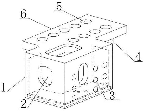
[0025] refer to figure 1 : A novel corner fitting, comprising a corner fitting 1 body, at least one side of the corner fitting 1 body is provided with a flange plate 6 extending along the edge of the body.
[0026] In this embodiment, a gap 4 is formed between the flange plate 6 and the body of the corner fitting 1 . Adjacent two sides of the corner fitting body extend outward to form flange plates. E.g: figure 1 In the corner piece, the two angled sides on the upper side of the corner piece extend outward to form a flange plate, and there is a gap between the flange plate and the two angled sides. In this embodiment, a flange plate is added on the original basis of the corner fitting, the strength of the corner fitting body can be increased by using the flange plate, and a plurality of first installation holes 5 can be set on the flange plate, and bolts can be used to secure the Corner fittings are fixed on columns and beams.
[0027] In this embodiment, a hoisting hole 2...
Embodiment 2
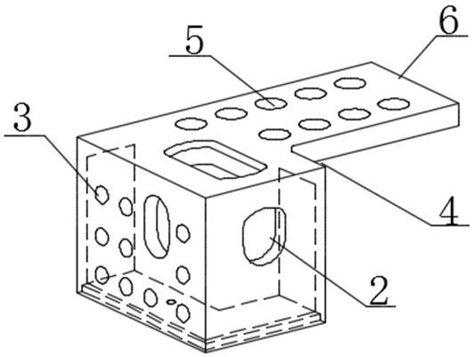
[0030] refer to figure 2 The difference between this embodiment and Embodiment 1 is that, in this embodiment, one side of the corner fitting body extends outward to form a flange plate. E.g, figure 2 In the corner piece, one side of the upper side of the corner piece extends outward to form a flange plate, and there is a gap between the flange plate and the side.
Embodiment 3
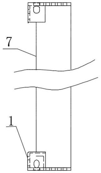
[0032] A connection structure of a novel corner fitting, comprising a first connecting body and a second connecting body, the first connecting body and the second connecting body are connected through at least one of the above-mentioned novel corner fittings.
[0033] The first connecting body is provided with a corner fitting body, and the flange plate of the corner fitting body is connected to the second connecting body through a threaded connection; or the flange plate of the corner fitting body is installed on the second connecting body The flange plate of the other corner fitting body is connected by a threaded connection.
[0034] The first connecting body and / or the second connecting body are connected to other components through the second mounting hole of the corner fitting body.
[0035] The first connecting body and the second connecting body are beams, columns, floor slabs or formwork structures.
[0036] Specifically, such as image 3 As shown, the flange plate ...
PUM
 Abstract
Description
Claims
Application Information
 - R&D Engineer
- R&D Manager
- IP Professional
- Industry Leading Data Capabilities
- Powerful AI technology
- Patent DNA Extraction
Browse by: Latest US Patents, China's latest patents, Technical Efficacy Thesaurus, Application Domain, Technology Topic, Popular Technical Reports.
© 2024 PatSnap. All rights reserved.Legal|Privacy policy|Modern Slavery Act Transparency Statement|Sitemap|About US| Contact US: help@patsnap.com


