
Load fastening structure and power control box using the structure

A technology for fastening structures and boxes, applied in the fields of non-rotational vibration suppression, vehicle parts, transportation and packaging, etc., can solve the problems of high processing cost of sheet metal bent frame and cannot meet the flexible and changeable needs of the market, and achieve Improve overall strength and avoid tearing effect

Active Publication Date: 2022-02-11
HEFEI UNIV OF TECH
View PDF10 Cites 0 Cited by
  • Summary
  • Abstract
  • Description
  • Claims
  • Application Information

AI Technical Summary

Problems solved by technology

The installation structure can only easily maintain the fastening position of the components on the outer frame in the width direction through the fixing of the bent frame, and the processing cost of the sheet metal bent frame is too high
[0005] Therefore, the common fixing methods in the prior art have their own limitations, cannot meet the flexible and changeable needs of the market, and need to be improved urgently.

Method used


Image

  • Load fastening structure and power control box using the structure
  • Load fastening structure and power control box using the structure
  • Load fastening structure and power control box using the structure

Examples


Embodiment Construction

[0040] The present invention will be further described in detail below in conjunction with the accompanying drawings and embodiments. It should be understood that the specific embodiments described here are only used to explain the present invention, but not to limit the present invention. In addition, it should be noted that, for the convenience of description, only some structures related to the present invention are shown in the drawings but not all structures.

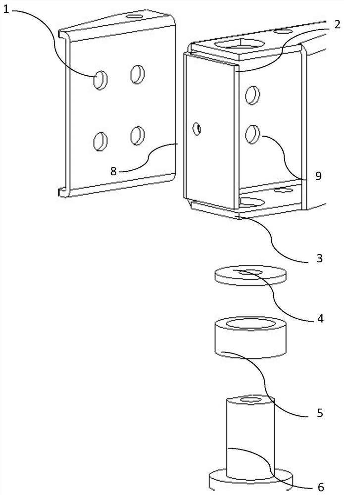
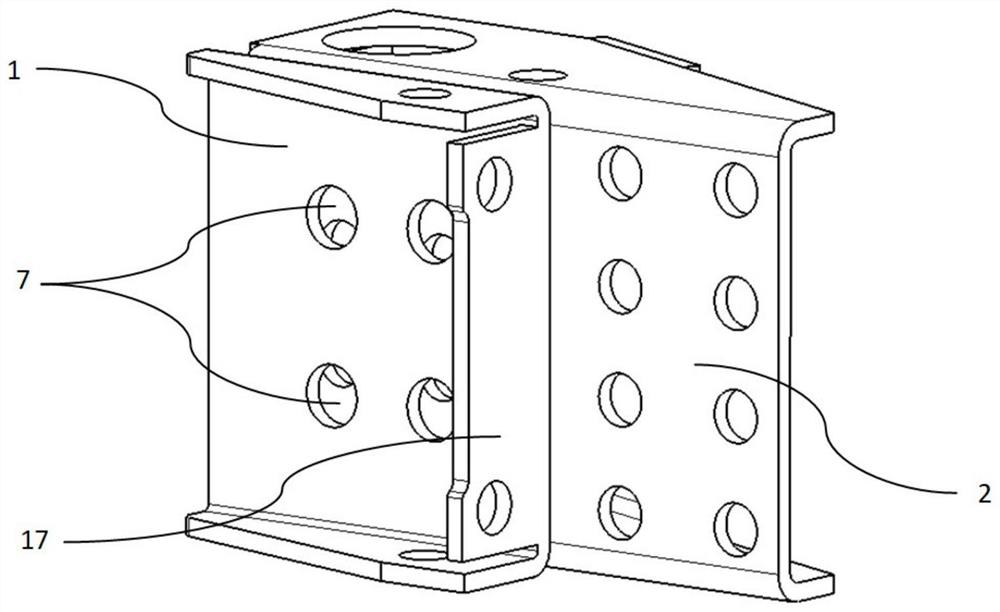
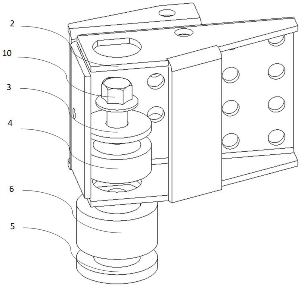
[0041] The present invention lies in: setting a load-bearing fastening structure comprising a combination of main bracket and auxiliary bracket, the mechanism is welded to each other to form an installation space with an included angle of 90 degrees, and the bolts crossing the main bracket and the auxiliary bracket horizontally and vertically are used to transmit the pressure to the The 4 fixed brackets on the outside of the 4 edges of the box body are then transmitted to the rubber shock absorbers below the bracke...


PUM


Abstract

A load-bearing fastening structure and an electric power control box using the structure, the load-bearing fastening mechanism includes a 90-degree angle of installation space formed by welding the main bracket and the auxiliary bracket to each other, and the horizontal and vertical intersection of the main bracket and the auxiliary bracket is used. The bolts transmit the pressure to the 4 fixed brackets on the outside of the 4 edges of the box, and then to the rubber shock absorbers under the brackets to limit the vibration transmitted from the body to the electric control unit. The shape and size of the main bracket and the auxiliary bracket of the present invention can be re-customized according to the requirements of different car models, so as to meet the requirements of allowing the same power control unit to be flexibly adapted to various different car models. Uniform distribution avoids the risk of box tearing; L-shaped angle steel and waterproof bolts are integrally welded to improve the overall strength; irregular fixing round holes act as a limit, so that sufficient torque can be applied to the bolts to fasten the shock-absorbing rubber piece.

Description

technical field [0001] The invention relates to the field of electric vehicles, in particular to a load-bearing fastening structure used in electric vehicles and a split-integrated power control box using the structure. Background technique [0002] The power control unit is an important part of the electric vehicle, and the design of the load-bearing fastening structure of the power control unit is directly related to the stable working state of each electrical component in the power control unit box. At present, the fastening of the power control unit is mainly by welding horizontal or vertical sheet metal beams on the bottom surface of the box body, and then fixing the sheet metal beams and the body girder by bolts to achieve the purpose of fixing the box body. [0003] The application number is CN201220492888.1, and the patent titled "A lower fixing structure for a hybrid power system control unit" provides a lower fixing structure for a hybrid power system control unit....

Claims


Application Information

Patent Timeline
Patent Type & Authority Patents(China)
IPC IPC(8): B60R11/00F16F15/08
CPCB60R11/00F16F15/08B60R2011/0052
Inventor 贺林俞圣杰石琴
Owner HEFEI UNIV OF TECH
Learn More